
DRYCAD Suite | User Documentation | v1.0.0
Table of Contents
- Overview
- Getting Started
- User Interface
- Configuration: settings.ini
- Examples
- Troubleshooting
- Version History
1. Overview
CATIA’s default workflow for adding Bodies and Geometrical Sets means navigating menus, accepting whatever generic name the application assigns, and cleaning up graphical properties afterwards, every single time. DRY0001 collapses all of that into one panel: pick the feature type, confirm the name, select a parent if needed, and you’re done. It also handles progressive numbering automatically, so you never end up with three things called Body.1.
What it does:
- Creates Bodies, Geometrical Sets, and Ordered Geometrical Sets inside the active CATIA V5 Part
- Pre-fills the name field with a configurable default and applies automatic case conversion at creation time
- Appends a numeric suffix when a feature with the same base name already exists
- Lets you target any Body or Geometrical Set as the parent, or reset to the top-level Part with one click
- Assigns a Boolean operation (Add, Assemble, Remove, Intersect) when inserting a Body inside another Body
- Applies color and line width automatically, based on your configuration, fixed, random, or none
- Sets the newly created feature as the active In Work Object and centers the CATIA display on it
Supported CAD platforms: CATIA V5
Workspace requirement: An active Part document must be open in CATIA.
2. Getting Started
Prerequisites
- CATIA V5 must be running
- You must be logged into the DRYCAD Suite
- An active Part document must be open in CATIA
Launching the Tool
DRY0001 is launched from the DRYCAD Suite CommandBar inside CATIA V5. Click the corresponding button to open the panel.
The tool checks the following conditions at startup, and will show an error and close if any fail:
- A valid user session is found, if not: “User not found. Please login and try again.”
- CATIA V5 is running and accessible, if not: “CATIA is not open. Please open CATIA and try again.”
- The active document is a Part, if not, an “Invalid Workspace” error is shown and the panel does not open
A background watchdog checks every 5 seconds whether CATIA is still running and whether the active document is still a Part. If either condition changes, the panel closes automatically.
The DRYCAD Menu
Every DRYCAD Suite tool with a user interface includes a menu in the top bar, accessed via the hamburger icon next to the window controls.

| Option | Description |
|---|---|
| Release 1.0.0 | Displays the current version of the tool. Informational only, not an action. |
| Documentation | Opens this documentation page in your default browser. |
| Open Settings | Opens settings.ini in your system’s default text editor. |
| Clear Settings | Resets settings.ini to a clean default version. Shows a confirmation warning before proceeding. |
3. User Interface
The panel is organized in four horizontal rows: feature type selection at the top, then name and color, then parent and Boolean operation, and finally the action buttons. The Name field receives keyboard focus automatically when the panel opens.
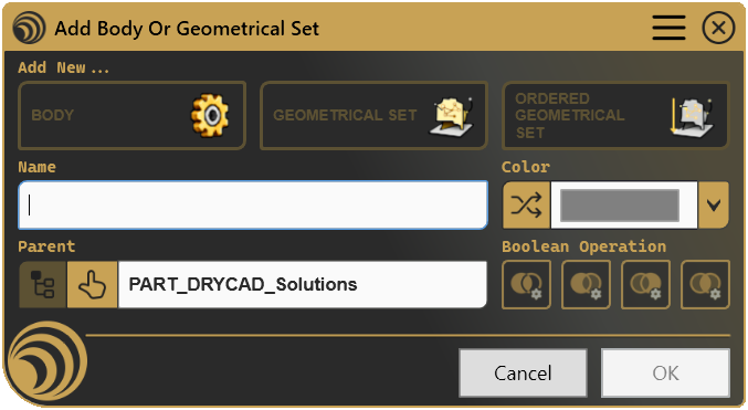
3.1 Add New, Feature Type Selection

Three toggle buttons let you choose what to create. Only one can be active at a time.
| Control | Icon | Description |
|---|---|---|
| BODY |  | Creates a standard solid Body |
| GEOMETRICAL SET |  | Creates a Geometrical Set for surface and wireframe geometry |
| ORDERED GEOMETRICAL SET |  | Creates an Ordered Geometrical Set |
Switching type also updates the Name field to the configured default for that type and reloads the Color picker with that type’s defaults. The Boolean Operation buttons are only enabled when BODY is active and the selected parent is not the top-level Part.
Note: The type shown on open is controlled by
DEFAULT_STARTING_FEATUREinsettings.ini. IfOVERRIDE_STARTING_FEATURE_ON_SELECTIONis enabled and a compatible object is selected in CATIA at launch, the type will match that selection instead.
3.2 Name and Color

The Name field is pre-filled with the configured default for the active feature type. You can edit it freely before confirming. Pressing Enter triggers OK.
If APPLY_PROGRESSIVE_NUMBERING is enabled, the tool searches the Part for existing features sharing the same base name and appends the first available numeric suffix, e.g. BODY becomes BODY.2, then BODY.3. Case conversion defined in settings.ini is applied at the moment of creation, not while typing.
The Color picker loads its palette from settings.ini. It can include fixed RGB or HEX colors, a no-color option (shown as transparent), and a random slot at the end.
| Control | Icon | Description |
|---|---|---|
| Random Color |  | Generates a new random color and selects it immediately |
| Color dropdown | - | Choose from the preconfigured palette |
If the default for the active type is set to RANDOM, a new random color is pre-selected each time the panel opens. Selecting the transparent slot means no graphical color is applied to the new feature.
3.3 Parent and Boolean Operation

The Parent field shows the object that will contain the new feature. By default this is the top-level Part.
| Control | Icon | Description |
|---|---|---|
| Reset to Top |  | Resets the parent to the top-level Part. Disabled when already at top level. |
| Select Parent |  | Prompts you to click a Body, Geometrical Set, or Ordered Geometrical Set in CATIA to use as the parent |
The parent field is read-only and truncates long names. The accepted parent types depend on the active feature type: for Ordered Geometrical Sets, only other Ordered Geometrical Sets or the Part root are valid.
The four Boolean Operation buttons are enabled only when BODY is active and the parent is not the top-level Part. Inserting a Body inside another Body requires one of these operations to be selected before OK becomes available.
| Control | Icon | Description |
|---|---|---|
| Add |  | Adds the new Body’s solid to the parent |
| Assemble |  | Assembles the new Body with the parent |
| Remove |  | Subtracts the new Body from the parent |
| Intersect |  | Intersects the new Body with the parent |
3.4 Cancel / OK
| Button | Action |
|---|---|
| Cancel | Closes the panel without making any changes to the CATIA document. |
| OK | Creates the feature, applies graphical properties, sets it as the In Work Object, and closes the panel. Also triggered by pressing Enter. |
OK is disabled if: no feature type is selected, the Name field is empty, or a Body is being inserted under a parent Body without a Boolean operation selected.
4. Configuration: settings.ini
File Location
<install_folder>/DRY0001/settings.iniCan also be opened directly via Open Settings in the DRYCAD Menu (see Section 2), or reset via Clear Settings.
Structure
; DRY0001 - ADD BODY OR GEOMETRICAL SET - SETTINGS FILE

[FeatureTypeSelection]
DEFAULT_STARTING_FEATURE=0
OVERRIDE_STARTING_FEATURE_ON_SELECTION=1

[NamingConventions]
DEFAULT_BODY_NAME="NEW BODY"
BODY_NAME_CASE_SELECTOR=1
DEFAULT_GEOSET_NAME="DRY_GEOSET"
GEOSET_NAME_CASE_SELECTOR=3
DEFAULT_ORDERED_GEOSET_NAME="DRY_Ordered_GeoSet"
ORDERED_GEOSET_NAME_CASE_SELECTOR=0
APPLY_PROGRESSIVE_NUMBERING=1
NUMBERING_SEPARATOR="."

[GraphicalProperties]
DEFAULT_BODY_COLOR=""
DEFAULT_BODY_LINEWIDTH=1
DEFAULT_GEOSET_COLOR="RANDOM"
DEFAULT_GEOSET_LINEWIDTH=1
DEFAULT_ORDERED_GEOSET_COLOR="50,100,150"
DEFAULT_ORDERED_GEOSET_LINEWIDTH=1

[BooleanProperties]
DEFAULT_BOOLEAN_OPERATION=0

[Colors]
CUSTOM_COLORS="ff0000 ff8000 ffff00 00ff00 00ffff 0000ff 7f00ff 000000 ffffff b0b0b0 808080 d4af35 94af57 cd8032"
Lines starting with ; are comments and are ignored.
Parameters
DEFAULT_STARTING_FEATURE
| Property | Value |
|---|---|
| Section | [FeatureTypeSelection] |
| Type | Integer (0–4) |
| Required | No |
| Default | 0 |
Controls which feature type is pre-selected when the panel opens.
; 0 = None (no type pre-selected)
; 1 = Previous Feature (remembers the last type used in the session)
; 2 = Body
; 3 = Geometrical Set
; 4 = Ordered Geometrical Set
DEFAULT_STARTING_FEATURE=2
OVERRIDE_STARTING_FEATURE_ON_SELECTION
| Property | Value |
|---|---|
| Section | [FeatureTypeSelection] |
| Type | Boolean (0 / 1) |
| Required | No |
| Default | 0 |
When set to 1, if a single compatible object is selected in CATIA at launch, the feature type is overridden to match, a selected Body opens the panel on BODY, a selected Geometrical Set opens it on GEOMETRICAL SET.
OVERRIDE_STARTING_FEATURE_ON_SELECTION=1DEFAULT_BODY_NAME
| Property | Value |
|---|---|
| Section | [NamingConventions] |
| Type | String |
| Required | No |
| Default | "BODY" |
The default name pre-filled in the Name field when BODY is the active type.
DEFAULT_BODY_NAME="SOLID_BODY"BODY_NAME_CASE_SELECTOR
| Property | Value |
|---|---|
| Section | [NamingConventions] |
| Type | Integer (0–3) |
| Required | No |
| Default | 0 |
Case conversion applied to the Body name at the moment of creation, not while typing.
; 0 = None
; 1 = Upper Case
; 2 = Lower Case
; 3 = Proper Case
BODY_NAME_CASE_SELECTOR=1
DEFAULT_GEOSET_NAME
| Property | Value |
|---|---|
| Section | [NamingConventions] |
| Type | String |
| Required | No |
| Default | "GEOMETRICAL_SET" |
The default name pre-filled when GEOMETRICAL SET is the active type.
DEFAULT_GEOSET_NAME="CONSTRUCTION"GEOSET_NAME_CASE_SELECTOR
| Property | Value |
|---|---|
| Section | [NamingConventions] |
| Type | Integer (0–3) |
| Required | No |
| Default | 0 |
Case conversion applied to the Geometrical Set name at creation. Same values as BODY_NAME_CASE_SELECTOR.
GEOSET_NAME_CASE_SELECTOR=3DEFAULT_ORDERED_GEOSET_NAME
| Property | Value |
|---|---|
| Section | [NamingConventions] |
| Type | String |
| Required | No |
| Default | "ORDERED_GEOSET" |
The default name pre-filled when ORDERED GEOMETRICAL SET is the active type.
DEFAULT_ORDERED_GEOSET_NAME="ORD_GS"ORDERED_GEOSET_NAME_CASE_SELECTOR
| Property | Value |
|---|---|
| Section | [NamingConventions] |
| Type | Integer (0–3) |
| Required | No |
| Default | 0 |
Case conversion applied to the Ordered Geometrical Set name at creation. Same values as BODY_NAME_CASE_SELECTOR.
ORDERED_GEOSET_NAME_CASE_SELECTOR=1APPLY_PROGRESSIVE_NUMBERING
| Property | Value |
|---|---|
| Section | [NamingConventions] |
| Type | Boolean (0 / 1) |
| Required | No |
| Default | 0 |
When set to 1, the tool searches the Part for existing features whose name starts with the same base name and appends the first available numeric suffix. The search covers the entire Part structure under the selected parent, not just the immediate level.
APPLY_PROGRESSIVE_NUMBERING=1NUMBERING_SEPARATOR
| Property | Value |
|---|---|
| Section | [NamingConventions] |
| Type | String (single character recommended) |
| Required | No |
| Default | "." |
The character inserted between the base name and the numeric suffix when progressive numbering is active.
; Results in: BODY.2, BODY.3
NUMBERING_SEPARATOR="."

; Results in: BODY_2, BODY_3
NUMBERING_SEPARATOR="_"
DEFAULT_BODY_COLOR
| Property | Value |
|---|---|
| Section | [GraphicalProperties] |
| Type | String |
| Required | No |
| Default | (empty) |
The default color applied to newly created Bodies. Three formats are accepted:
DEFAULT_BODY_COLOR=""           ; no color applied
DEFAULT_BODY_COLOR="RANDOM"     ; random color on every open
DEFAULT_BODY_COLOR="255,128,0"  ; fixed RGB (values 0–255)
DEFAULT_BODY_COLOR="ff8000"     ; fixed HEX (6 digits)
DEFAULT_BODY_LINEWIDTH
| Property | Value |
|---|---|
| Section | [GraphicalProperties] |
| Type | Integer (1–8) |
| Required | No |
| Default | 1 |
The line width applied to newly created Bodies. Valid values are 1 through 8, matching CATIA’s standard line width levels.
DEFAULT_BODY_LINEWIDTH=2DEFAULT_GEOSET_COLOR
| Property | Value |
|---|---|
| Section | [GraphicalProperties] |
| Type | String |
| Required | No |
| Default | (empty) |
The default color applied to newly created Geometrical Sets. Same format as DEFAULT_BODY_COLOR.
DEFAULT_GEOSET_COLOR="RANDOM"DEFAULT_GEOSET_LINEWIDTH
| Property | Value |
|---|---|
| Section | [GraphicalProperties] |
| Type | Integer (1–8) |
| Required | No |
| Default | 1 |
The line width applied to newly created Geometrical Sets.
DEFAULT_GEOSET_LINEWIDTH=1DEFAULT_ORDERED_GEOSET_COLOR
| Property | Value |
|---|---|
| Section | [GraphicalProperties] |
| Type | String |
| Required | No |
| Default | (empty) |
The default color applied to newly created Ordered Geometrical Sets. Same format as DEFAULT_BODY_COLOR.
DEFAULT_ORDERED_GEOSET_COLOR="50,100,150"DEFAULT_ORDERED_GEOSET_LINEWIDTH
| Property | Value |
|---|---|
| Section | [GraphicalProperties] |
| Type | Integer (1–8) |
| Required | No |
| Default | 1 |
The line width applied to newly created Ordered Geometrical Sets.
DEFAULT_ORDERED_GEOSET_LINEWIDTH=1DEFAULT_BOOLEAN_OPERATION
| Property | Value |
|---|---|
| Section | [BooleanProperties] |
| Type | Integer (0–5) |
| Required | No |
| Default | 0 |
The Boolean operation pre-selected when inserting a Body inside another Body.
; 0 = None (no operation pre-selected)
; 1 = Previous Selection (remembers the last operation used in the session)
; 2 = Add
; 3 = Assemble
; 4 = Remove
; 5 = Intersect
DEFAULT_BOOLEAN_OPERATION=3
CUSTOM_COLORS
| Property | Value |
|---|---|
| Section | [Colors] |
| Type | Space-separated list of HEX or RGB color strings |
| Required | No |
| Default | (empty) |
Additional colors shown in the Color dropdown, after the default color and the no-color slot. A random color slot is always appended at the end automatically. Colors can be 6-digit HEX or R,G,B (0–255).
CUSTOM_COLORS="ff0000 00ff00 0000ff 128,128,128"5. Examples
Example 1, Body-First Team, Assemble Default
A team that works predominantly with Bodies and always assembles them. Names are forced to upper case; progressive numbering is on.
[FeatureTypeSelection]
DEFAULT_STARTING_FEATURE=2
OVERRIDE_STARTING_FEATURE_ON_SELECTION=1

[NamingConventions]
DEFAULT_BODY_NAME="BODY"
BODY_NAME_CASE_SELECTOR=1
DEFAULT_GEOSET_NAME="GEO_SET"
GEOSET_NAME_CASE_SELECTOR=1
DEFAULT_ORDERED_GEOSET_NAME="ORD_GS"
ORDERED_GEOSET_NAME_CASE_SELECTOR=1
APPLY_PROGRESSIVE_NUMBERING=1
NUMBERING_SEPARATOR="."

[GraphicalProperties]
DEFAULT_BODY_COLOR=""
DEFAULT_BODY_LINEWIDTH=1
DEFAULT_GEOSET_COLOR=""
DEFAULT_GEOSET_LINEWIDTH=1
DEFAULT_ORDERED_GEOSET_COLOR=""
DEFAULT_ORDERED_GEOSET_LINEWIDTH=1

[BooleanProperties]
DEFAULT_BOOLEAN_OPERATION=3

[Colors]
CUSTOM_COLORS=""
What it creates: A Body named BODY (or BODY.2, BODY.3, etc. when names already exist), with no color and Assemble pre-selected as the Boolean operation.
Key points:
DEFAULT_STARTING_FEATURE=2opens the panel on the Body type every time, no clicking requiredBODY_NAME_CASE_SELECTOR=1guarantees upper case regardless of how the name is typedDEFAULT_BOOLEAN_OPERATION=3pre-selects Assemble, covering the most common insertion scenario- Empty
CUSTOM_COLORSmeans the dropdown shows only the no-color option and a random slot
Example 2, Geometrical Sets with Random Colors
A designer who uses Geometrical Sets for construction geometry and wants each set to have a visually distinct random color. Progressive numbering uses underscore separator.
[FeatureTypeSelection]
DEFAULT_STARTING_FEATURE=3
OVERRIDE_STARTING_FEATURE_ON_SELECTION=1

[NamingConventions]
DEFAULT_BODY_NAME="BODY"
BODY_NAME_CASE_SELECTOR=0
DEFAULT_GEOSET_NAME="CONSTRUCTION"
GEOSET_NAME_CASE_SELECTOR=3
DEFAULT_ORDERED_GEOSET_NAME="ORDERED_GS"
ORDERED_GEOSET_NAME_CASE_SELECTOR=0
APPLY_PROGRESSIVE_NUMBERING=1
NUMBERING_SEPARATOR="_"

[GraphicalProperties]
DEFAULT_BODY_COLOR=""
DEFAULT_BODY_LINEWIDTH=1
DEFAULT_GEOSET_COLOR="RANDOM"
DEFAULT_GEOSET_LINEWIDTH=2
DEFAULT_ORDERED_GEOSET_COLOR=""
DEFAULT_ORDERED_GEOSET_LINEWIDTH=1

[BooleanProperties]
DEFAULT_BOOLEAN_OPERATION=0

[Colors]
CUSTOM_COLORS="ff0000 ff8000 ffff00 00ff00 00ffff 0000ff 7f00ff"
What it creates: A Geometrical Set named Construction (Proper Case applied), assigned a random color, with line width 2. The second one becomes Construction_2.
Key points:
DEFAULT_STARTING_FEATURE=3opens directly on Geometrical Set typeGEOSET_NAME_CASE_SELECTOR=3(Proper Case) means typingconstruction dataproducesConstruction DataDEFAULT_GEOSET_COLOR="RANDOM"selects a new color on every panel open, no manual picking neededNUMBERING_SEPARATOR="_"producesConstruction_2instead ofConstruction.2
Example 3, Mixed Team with Company Color Standards
A larger team where different designers create different feature types. The tool adapts to whatever is selected in CATIA, and a shared company color palette enforces visual consistency.
[FeatureTypeSelection]
DEFAULT_STARTING_FEATURE=1
OVERRIDE_STARTING_FEATURE_ON_SELECTION=1

[NamingConventions]
DEFAULT_BODY_NAME="COMP_BODY"
BODY_NAME_CASE_SELECTOR=1
DEFAULT_GEOSET_NAME="COMP_GS"
GEOSET_NAME_CASE_SELECTOR=1
DEFAULT_ORDERED_GEOSET_NAME="COMP_OGS"
ORDERED_GEOSET_NAME_CASE_SELECTOR=1
APPLY_PROGRESSIVE_NUMBERING=1
NUMBERING_SEPARATOR="."

[GraphicalProperties]
DEFAULT_BODY_COLOR="50,100,200"
DEFAULT_BODY_LINEWIDTH=2
DEFAULT_GEOSET_COLOR="200,100,50"
DEFAULT_GEOSET_LINEWIDTH=1
DEFAULT_ORDERED_GEOSET_COLOR="50,150,50"
DEFAULT_ORDERED_GEOSET_LINEWIDTH=1

[BooleanProperties]
DEFAULT_BOOLEAN_OPERATION=1

[Colors]
CUSTOM_COLORS="3264c8 c86432 329632 c8c832 c83264 646464"
What it creates: The starting type follows the current CATIA selection (or falls back to the previous session type). Each feature type gets a company-standard color, blue for Bodies, orange for Geometrical Sets, green for Ordered Geometrical Sets.
Key points:
DEFAULT_STARTING_FEATURE=1combined withOVERRIDE_STARTING_FEATURE_ON_SELECTION=1makes the tool context-aware: it opens on the type matching the current selection, and remembers the last used type when nothing is selectedDEFAULT_BOOLEAN_OPERATION=1(Previous Selection) remembers each designer’s last Boolean operation across the session- Fixed RGB colors per type enforce a visual standard without relying on manual selection
CUSTOM_COLORSmirrors the same company colors in HEX for manual override when needed
6. Troubleshooting
”User not found. Please login and try again.”
The tool could not identify the logged-in user at startup. Log out of the DRYCAD Suite, log back in, and relaunch.
”CATIA is not open. Please open CATIA and try again.”
The tool launched but could not find a running CATIA V5 process. Make sure CATIA is fully loaded before clicking the CommandBar button.
”Invalid Workspace”
The active document is not a Part. DRY0001 only operates on Part documents. Switch to or open a Part in CATIA, then relaunch.
Panel closes unexpectedly without any action
The background watchdog detected that CATIA has closed, or the active document is no longer a Part (e.g. you switched to a Drawing or Product). This is expected behavior, the panel shuts down to avoid operating on an unsupported context. Return to a Part document and reopen the panel.
OK button stays disabled
Check all of the following:
- A feature type must be selected, one of the three type buttons must be active
- The Name field must not be empty
- If inserting a Body under a parent Body (the Parent field shows a Body name, not the Part root), a Boolean operation must be selected
The new feature has the wrong name case
Case conversion is applied at the moment you click OK, not while typing. The name in the field is your raw input; the converted version is what ends up in CATIA. Check BODY_NAME_CASE_SELECTOR, GEOSET_NAME_CASE_SELECTOR, or ORDERED_GEOSET_NAME_CASE_SELECTOR in settings.ini.
Progressive numbering skips numbers or jumps unexpectedly
If the tool creates BODY.4 when you expected BODY.2, features with intermediate names already exist somewhere in the Part tree, possibly inside nested structures not visible in the current view. The search covers the entire Part under the selected parent, not just the immediate level.
No color is applied even though one appears selected
Check that the selected item in the Color dropdown is not the empty (transparent) slot, that option intentionally applies no color. Also verify that the relevant DEFAULT_*_COLOR parameter in settings.ini is not set to "" if you want a color applied by default.
7. Version History
| Version | Date | Changes |
|---|---|---|
| 1.0.0 | 2026-06 | Initial release |
DRY0001, Add Body or Geometrical Set | DRYCAD Solutions | v1.0.0