
DRYCAD Suite | User Documentation | v1.0.0
Table of Contents
- Overview
- Getting Started
- User Interface
- Configuration: settings.ini
- Configuration: Structures File
- Examples
- Troubleshooting
- Version History
1. Overview
DRY0002 – Add Structured Item is a CATIA V5 automation tool that lets you insert predefined hierarchical part structures, Bodies, Geometrical Sets, and Ordered Geometrical Sets, into an active part with a single click.
Instead of manually creating and naming structural elements one by one every time you start a new part or feature, you define your standard structures once in a configuration file. The tool reads that file and lets you pick the structure you need, optionally rename the key element, optionally choose a parent object, and insert everything in one operation.
What it does:
- Inserts nested hierarchies of Bodies, Geometrical Sets, and Ordered Geometrical Sets
- Applies graphical properties (color, opacity, line width, line style, point style) automatically
- Optionally searches for and updates existing elements rather than creating duplicates
- Supports Boolean insert modes for Bodies (Add, Assemble, Remove, Intersect)
- Creates Empty Joins inside Geometrical Sets when needed
- Re-focuses the in-work object automatically after insertion
Supported CAD platforms: CATIA V5
Workspace requirement: An active Part document must be open in CATIA.
2. Getting Started
Prerequisites
- CATIA V5 must be running with at least one Part document open
- You must be logged in with a valid DRYCAD Suite user account
- A valid Structures File must exist and its path must be set in
settings.ini(see Section 4)
Launching the Tool
DRY0002 is launched from the DRYCAD Suite CommandBar inside CATIA V5. Click the corresponding button to open the panel.
The tool checks the following conditions at startup, and will show an error and close if any fail:
- A valid user session is found
- CATIA V5 is running
- The active document is a Part (not a Product, Drawing, or other workspace)
If the settings.ini path to the Structures File is missing or incorrect, the tool will open but display a warning. You will need to fix the configuration before structures can be loaded.
The DRYCAD Menu
Every DRYCAD Suite tool with a user interface includes a menu in the top bar, accessed via the hamburger icon next to the window controls.

| Option | Description |
|---|---|
| Release 1.0.0 | Displays the current version of the tool. Informational only, not an action. |
| Documentation | Opens this documentation page in your default browser. |
| Open Settings | Opens settings.ini in your system’s default text editor. |
| Clear Settings | Resets settings.ini to a clean default version. Shows a confirmation warning before proceeding. |
3. User Interface
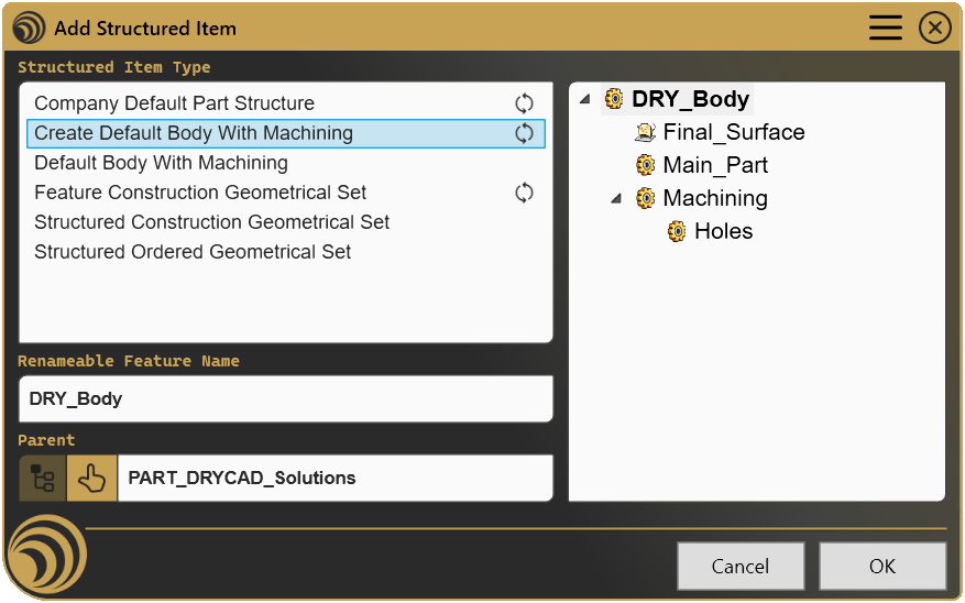
The panel is divided into two columns. The left column contains the controls; the right column shows a live tree preview of the selected structure.
3.1 Structured Item Type (List)

Displays all the structures defined in your Structures File. Each entry corresponds to one [START]...[END] block.
- Select an entry to load it. The tree preview on the right updates immediately.
- Entries marked with the update icon

UPDATE_EXISTING=1).
3.2 Renameable Feature Name (Text Field)

Some structures define one element as renameable, typically the main Body or the top-level Geometrical Set. When a renameable element exists, this field becomes active and pre-filled with the default name from the configuration.
- Edit the field to give the element a custom name before inserting.
- The tree preview updates live as you type.
- If no renameable element is defined in the selected structure, the field is greyed out and read-only.
Note: The renameable element is shown in bold in the tree preview.
3.3 Parent Selection

Controls where in the part tree the structure will be inserted.
| Control | Icon | Description |
|---|---|---|
| Reset to Top |  | Resets the parent to the top-level Part node. Active only when a non-top-level parent is currently selected. |
| Select Parent |  | Prompts you to click an element in the CATIA specification tree to use as the parent. Only available when the selected structure allows parent selection (ALLOW_PARENT_SELECTION=1). The accepted types (Body, Geometrical Set, Ordered Geometrical Set) are defined per structure. |
| Parent Name field | - | Read-only display of the currently selected parent. Shows the Part name when the top level is selected. |
3.4 Tree Preview

A live, read-only hierarchical view of the structure that will be inserted. Updates immediately when you change the selected structure or the renameable name.
Each node displays a type icon indicating the element type:
| Icon | Element Type |
|---|---|
 | Body |
 | Geometrical Set |
 | Ordered Geometrical Set |
 | Empty Join |
The renameable element is displayed in bold. The tree is always fully expanded.
3.5 Cancel / OK
| Button | Action |
|---|---|
| Cancel | Closes the panel without making any changes to the part. |
| OK | Inserts the selected structure into the active part and closes the panel. Disabled until a structure is selected. Also triggered by pressing Enter. |
4. Configuration: settings.ini
Located in the tool’s installation folder, settings.ini is the main configuration file for DRY0002. It is a plain text file you can edit with any text editor.
File Location
<install_folder>/DRY0002/settings.iniCan also be opened directly via Open Settings in the DRYCAD Menu (see Section 2), or reset via Clear Settings.
Structure
; ----------------------------------------------
; DRY0002 - ADD STRUCTURED ITEMS - SETTINGS FILE
; ----------------------------------------------

[File Location]
; STRUCTURED ITEMS TEXT FILE LOCATION
DEFAULT_FILE_LOCATION="D:\path\to\your\DefaultStructures.txt"
Lines starting with ; are comments and are ignored.
Parameters
DEFAULT_FILE_LOCATION
| Property | Value |
|---|---|
| Section | [File Location] |
| Type | File path (string) |
| Required | Yes |
| Default | (empty, must be set manually) |
The full path to your Structures File, the text file that defines all available structures (see Section 5).
The path must point to an existing .txt file and can be either an absolute path or a network path. Enclose the path in double quotes if it contains spaces.
; Local path
DEFAULT_FILE_LOCATION="C:\DRYCAD\Structures\DefaultStructures.txt"

; Network path (shared company configuration)
DEFAULT_FILE_LOCATION="\\server\drycad\configs\CompanyStructures.txt"
Tip for teams: Point all users to the same file on a shared network drive. Any update to the file is immediately available to everyone without reinstalling or reconfiguring.
5. Configuration: Structures File
The Structures File is a plain text file (.txt) that defines all the structures available in the tool’s list. You can have as many structures as you need. The file path is set in settings.ini.
5.1 File Syntax Overview
The file is made up of independent blocks. Each block defines one structure entry.
; Lines starting with ; are comments

[START]
  ... structure definition ...
[END]

[START]
  ... another structure ...
[END]
Blank lines and comment lines (;) outside blocks are ignored. Order in the file determines order in the tool’s list.
5.2 Block Header Parameters
These go between [START] and the opening {, one per line, using KEY=VALUE syntax.
| Parameter | Required | Values | Description |
|---|---|---|---|
NAME | Yes | Any string | Display name shown in the tool’s list |
UPDATE_EXISTING | No | 0 or 1 | If 1, the tool searches for existing elements with matching names before creating new ones. Matched elements are renamed if needed but not duplicated. Default: 0 |
ALLOW_PARENT_SELECTION | No | 0 or 1 | If 1, the Parent selection buttons are enabled for this structure. Default: 0 |
PARENT_SELECTION_TYPE | No | Body, GeometricalSet, OrderedGeometricalSet (comma-separated) | Filters which element types the user can select as a parent. Only used when ALLOW_PARENT_SELECTION=1 |
Example:
[START]
NAME=My Custom Structure
UPDATE_EXISTING=1
ALLOW_PARENT_SELECTION=1
PARENT_SELECTION_TYPE=Body,GeometricalSet
{
    ...
}
[END]
5.3 Structure Definition (the { } block)
The hierarchy of elements to create is defined inside curly braces { }. Each line defines one element.
Line Format
<level>-<ItemType>[<UpdateMode>]///Key=Value///Key=Value///...<level>, integer (starting at1) indicating the depth in the hierarchy. Level1is the root. A level-2element is a child of the nearest preceding level-1element, and so on.<ItemType>, the type of element to create (see below)[<UpdateMode>], optional, only forBODYand geometrical sets. Write[Update]to allow this specific element to be matched and updated if it already exists (requiresUPDATE_EXISTING=1on the block header)///, separator between the type declaration and properties, and between properties
Item Types
| Icon | Type | Description |
|---|---|---|
| | BODY | Creates a standard Body |
| | BODY.ADD | Creates a Body with an Add Boolean operation |
| | BODY.ASSEMBLE | Creates a Body with an Assemble Boolean operation |
| | BODY.REMOVE | Creates a Body with a Remove Boolean operation |
| | BODY.INTERSECT | Creates a Body with an Intersect Boolean operation |
| | GEOSET | Creates a Geometrical Set |
| | ORDGEOSET | Creates an Ordered Geometrical Set |
| | EMPTYJOIN | Creates an inactive Empty Join inside a Geometrical Set or Ordered Geometrical Set |
For Boolean Bodies, you can optionally name the Boolean operation node by appending (name) after the type:
2-BODY.ADD(Add->> Main_Part)///Name=Main_Part5.4 Element Properties
Properties follow the item type, separated by ///. Any property can be omitted; defaults apply.
Name / Name*
///Name=MyBody
///Name*=MyBody
The name of the element as it will appear in the CATIA specification tree.
Name, fixed name, not editable by the user in the panelName*, marks this element as renameable. The name field in the panel becomes active and pre-filled with this value. Only one element per structure should be marked renameable.
Using * as the name value (Name=*) on a non-renameable element will automatically mirror the name of the renameable element (uppercased). Useful for keeping a Boolean node name in sync with its Body name.
Color
///Color=202,161,100
///Color=Random
///Color=Parent
Sets the graphical color of the element.
| Value | Description |
|---|---|
R,G,B | Explicit RGB values (0–255 each) |
Random | Assigns a random color each time the structure is inserted |
Parent | Inherits and slightly shifts the color of the parent element |
Opacity
///Opacity=1.0Sets the transparency of the element. Range: 0.0 (fully transparent) to 1.0 (fully opaque).
Linewidth
///Linewidth=1Sets the line width using CATIA’s integer line width index.
LineStyle
///LineStyle=4Sets the line style using CATIA’s integer line style index (e.g., 4 = dashed).
PointStyle
///PointStyle=4Sets the point representation style using CATIA’s integer point style index.
InWorkObject
///InWorkObject=1If 1, this element becomes the active In-Work Object in CATIA after insertion. Only one element per structure should use this. If not set on any element, CATIA’s default In-Work Object behavior applies.
MainBody
///MainBody=1If 1, this Body is set as the Part’s Main Body. Only applies to BODY type elements.
CaseSelector
///CaseSelector=1Controls automatic case conversion applied to the renameable element’s name when the user types it.
| Value | Behaviour |
|---|---|
0 | No conversion (default) |
1 | UPPERCASE |
2 | lowercase |
3 | Title Case |
5.5 Full Block Syntax Reference
[START]
NAME=<Display Name>
UPDATE_EXISTING=<0|1>
ALLOW_PARENT_SELECTION=<0|1>
PARENT_SELECTION_TYPE=<Body|GeometricalSet|OrderedGeometricalSet,...>
{
    1-<ItemType>[Update]///Name[*]=<name>///Color=<R,G,B|Random|Parent>///Opacity=<0.0-1.0>///Linewidth=<n>///LineStyle=<n>///PointStyle=<n>///InWorkObject=<0|1>///MainBody=<0|1>///CaseSelector=<0|1|2|3>
        2-<ItemType>///Name=<name>///...
            3-<ItemType>///Name=<name>///...
}
[END]
6. Examples
The following examples are drawn from the default configuration file included with DRY0002.
Example 1, Company Default Part Structure
A large, fixed structure intended to set up a complete standard part from scratch. No parent selection, no renaming, it always creates the same thing at the top level.
[START]
NAME=Company Default Part Structure
UPDATE_EXISTING=1
{
    1-GEOSET///Name=Common_Geometry///Color=202,161,100///Opacity=1.0///Linewidth=1
        2-GEOSET///Name=Isolated_References///Color=64,64,64
        2-GEOSET///Name=Points///PointStyle=4
        2-GEOSET///Name=Axes///LineStyle=4
        2-GEOSET///Name=Planes///Color=128,255,128///Linewidth=2
        2-GEOSET///Name=Sketches///Linewidth=2
            3-GEOSET///Name=Reference_Sketches
            3-GEOSET///Name=Grouped_Points
        2-GEOSET///Name=Surfaces
    1-GEOSET///Name=Construction_Geometry///Color=202,161,100///Opacity=1
    1-BODY///Name*=DRY_Body///Color=202,161,100///Opacity=1.0///Linewidth=1///MainBody=1
        2-GEOSET///Name=Final_Surface///Color=0,128,128///Linewidth=1
        2-BODY.ADD(Add->> Main_Part)///Name=Main_Part
        2-BODY.REMOVE(Remove->> Machining)///Name=Machining///Color=94,81,65
            3-BODY.ASSEMBLE(Assemble->> Holes)///Name=Holes
}
[END]
What it creates:
- Two root Geometrical Sets (
Common_GeometryandConstruction_Geometry), each with their sub-sets - A main Body (name editable by the user, shown bold in the tree), set as the Part’s Main Body, with nested Bodies for machining and holes using Boolean operations
Key points:
UPDATE_EXISTING=1, ifCommon_Geometryalready exists, it won’t be duplicatedName*=DRY_Bodyon the Body, the user can rename it from the panel before insertingMainBody=1, this Body becomes the Part’s Main Body
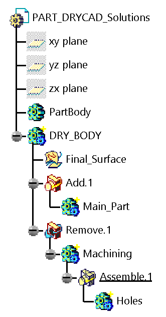
Example 2, Create Default Body With Machining
A leaner structure for adding a new Body with a standard machining sub-structure to an existing part. The user can target a specific existing Body as the parent.
[START]
NAME=Create Default Body With Machining
UPDATE_EXISTING=1
ALLOW_PARENT_SELECTION=1
PARENT_SELECTION_TYPE=Body
{
    1-BODY[Update]///Name*=DRY_Body///Color=Random///Opacity=1.0///Linewidth=1///CaseSelector=1
        2-GEOSET///Name=Final_Surface///Color=0,128,128///Linewidth=1
        2-BODY.ADD///Name=Main_Part
        2-BODY.REMOVE///Name=Machining///Color=Parent
            3-BODY.ASSEMBLE///Name=Holes
}
[END]
Key points:
ALLOW_PARENT_SELECTION=1+PARENT_SELECTION_TYPE=Body, the user can click an existing Body in the tree to insert the new structure inside itColor=Randomon the root Body, a different color every time, useful when inserting multiple bodiesColor=ParentonMachining, automatically inherits and tones down the parent Body’s random color for visual coherence[Update]on the root Body, if a Body with the given name already exists under the selected parent, it is updated rather than duplicatedCaseSelector=1, whatever name the user types is automatically converted to UPPERCASE
Result in the CATIA tree:
Example 3, Feature Construction Geometrical Set
A utility structure for adding a standardized construction geometry sub-set inside an existing Body or Geometrical Set. Includes an Empty Join as a placeholder.
[START]
Name=Feature Construction Geometrical Set
UPDATE_EXISTING=1
ALLOW_PARENT_SELECTION=1
PARENT_SELECTION_TYPE=Body,GeometricalSet
{
    1-GEOSET[Update]///Name=Construction_Geometry///Color=202,161,100///Opacity=1
        2-GEOSET///Name*=New Geometrical Set///Linewidth=1///CaseSelector=3
            3-GEOSET///Name=Construction
            3-EMPTYJOIN///Name=*
}
[END]
Key points:
- The root
GEOSETis namedConstruction_Geometryand uses[Update], it finds and reuses an existing set with that name rather than creating a duplicate - The level-2
GEOSETis renameable (Name*) with Title Case conversion (CaseSelector=3) - The
EMPTYJOINusesName=*, it will be automatically named after the renameable element (uppercased), keeping the join’s name consistent with its parent set
7. Troubleshooting
”User not found. Please login and try again.”
The tool could not find a valid DRYCAD Suite user session. Make sure you are logged in to the Suite before launching the tool.
”CATIA is not open. Please open CATIA and try again.”
The tool cannot connect to a running CATIA V5 instance. Launch CATIA V5 first, then run the macro.
”Invalid Workspace”
The active document in CATIA is not a Part. DRY0002 only works inside a Part document. Close any Drawing, Product, or other document type and make sure a Part is active before launching.
Warning: “Configuration setup path is missing.”
The DEFAULT_FILE_LOCATION key in settings.ini is empty or not set. The tool opens but the structure list will be empty. Edit settings.ini and set the correct path to your Structures File, then relaunch the tool.
The structure list is empty (no warning shown)
The Structures File path in settings.ini is set but the file cannot be read, or the file contains no valid [START]...[END] blocks. Check that:
- The path in
settings.iniis correct and the file exists - Every block has both a
[START]and[END]marker - Every block has a
{...}section with at least one valid element line - No element line is missing both a type declaration and a
Name/Name*property
The tool closes automatically after a few seconds
DRY0002 monitors the CATIA process and the active workspace every 5 seconds. It will close automatically if:
- CATIA is closed while the panel is open
- The active document changes away from a Part (e.g., you switch to a Drawing or Product)
This is by design to prevent the tool from operating on an invalid workspace.
An element is not being created
Some combinations of parent type and element type are not supported by CATIA and are silently skipped:
- A
BODYorORDGEOSETcannot be created inside a Geometrical Set - An
EMPTYJOINrequires a parent that is aGEOSETorORDGEOSET
Review your structure definition and ensure the hierarchy is compatible with CATIA’s rules.
8. Version History
| Version | Date | Changes |
|---|---|---|
| 1.0.0 | 2026-06 | Initial release |
DRY0002, Add Structured Item | DRYCAD Solutions | v1.0.0