
DRYCAD Suite | User Documentation | v1.0.0
Table of Contents
- Overview
- Getting Started
- How It Works
- Configuration: settings.ini
- Configuration: Secondary File
- Examples
- Troubleshooting
- Version History
1. Overview
Bounding Volume Generator measures a selected body and builds a rectangular solid that wraps it exactly, not aligned to the absolute X, Y, Z axes, but to the body’s own center of gravity and principal inertia axes. That means a part sitting at an odd angle still gets a tight, meaningful envelope instead of an oversized box padded out by its rotation.
What it does:
- Calculates the true bounding volume of a selected body from its center of gravity and principal axes.
- Creates a solid body representing that volume directly in the Part, named with its own computed dimensions.
- Optionally grows the volume by a fixed margin on every face, for clearance checks or packaging references.
Supported CAD platforms: CATIA V5
Workspace requirement: An active Part document must be open in CATIA, containing at least one solid body to analyze.
2. Getting Started
Prerequisites
- CATIA V5 is running with a Part document open.
- The Part contains at least one solid body with a non-zero volume.
Launching the Tool
DRY0018 is launched from the DRYCAD Suite CommandBar inside CATIA V5. Click the corresponding button to run it.
The tool checks the following conditions at startup, and will show an error and close if any fail:
- A recognized user is logged in.
- CATIA is open and reachable.
- The active workspace is a Part document.
Unlike most Suite tools, DRY0018 has no separate panel to configure before it runs. Once launched, it works through a short sequence of native CATIA prompts instead of a custom interface, covered step by step below.
3. How It Works
3.1 Replacing an Existing Bounding Volume
If a bounding volume body already exists in the current Part (matching the name configured by DEFAULT_BOUNDING_VOLUME_BODY_NAME), the tool shows a confirmation dialog before doing anything else:
A Bounding Box Volume already exists in the current Part. Do you want to replace it?
Choosing Yes deletes the existing bounding body along with any leftover bounding-volume axis systems from a previous run, then continues. Choosing No closes the tool immediately, leaving the Part untouched.
This check exists so every run starts from a clean state, a stale bounding volume from an earlier version of the Part is never left mixed in with a new one.
3.2 Selecting the Body to Analyze
Next, DRY0018 prompts you to select the body to wrap, using CATIA’s native selection, the same prompt-in-the-3D-view interaction as any other selection request.
Bodies whose names start with a prefix or end with a suffix listed in BODY_NAME_PREFIXES_TO_IGNORE / BODY_NAME_SUFFIXES_TO_IGNORE (see Section 4) are excluded from consideration entirely, useful for keeping hardware, datum, or insert bodies out of the selection by convention rather than by remembering to skip them each time.
Once selected, the tool validates the body by measuring its volume. If the measured volume is zero, an empty body, a surface-only body, or one containing only wireframe or points, the tool stops silently, without any error message. This is the single most common reason nothing appears to happen after a selection; see Troubleshooting.
3.3 Measuring and Building the Volume
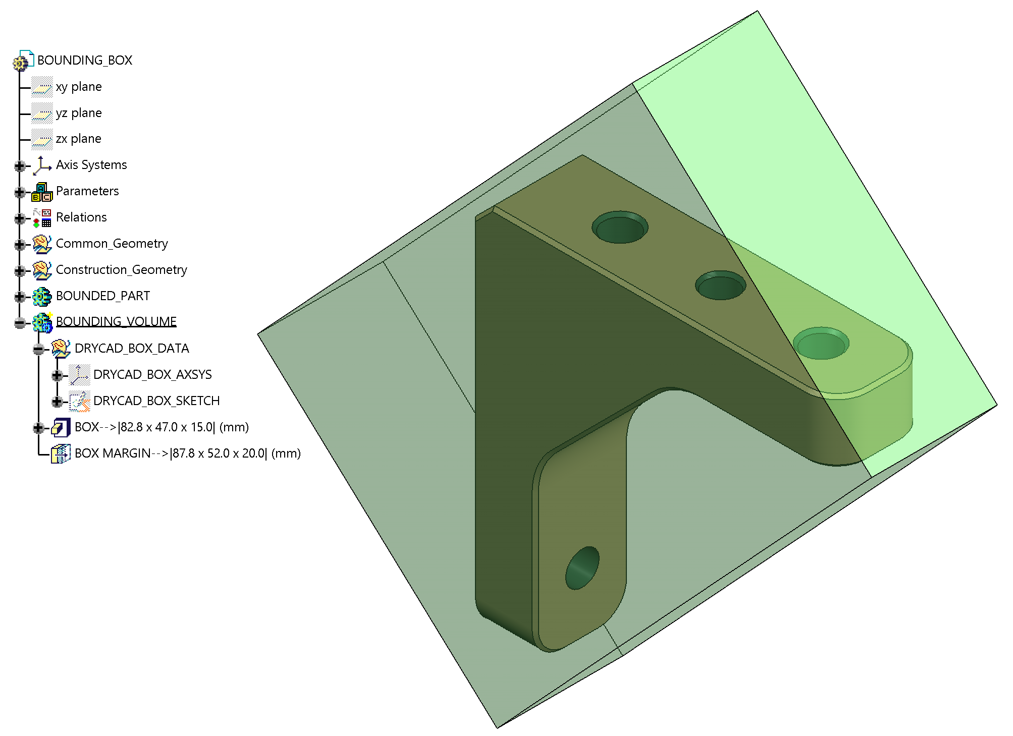
DRY0018 briefly opens CATIA’s native Measure Inertia panel on the selected body to read its center of gravity and principal axis vectors, then closes the panel automatically once the values are captured, you won’t need to interact with it yourself. From those values, the tool builds:
- An axis system at the body’s center of gravity, oriented to its principal axes.
- A sketch and a solid pad sized to the body’s true extents along that orientation.
- If
BOUNDING_VOLUME_THICKNESSis set to a non-zero value, an additional thickness feature that grows the volume outward on every face by that margin.
3.4 Result Naming
The generated pad is named with its own computed dimensions, for example:
BOX-->|120.0 x 45.0 x 30.0| (mm)If a margin was applied, the thickness feature is named the same way, using the enlarged dimensions:
BOX MARGIN-->|125.0 x 50.0 x 35.0| (mm)Reading the size straight off the tree means never having to re-measure it later.
4. Configuration: settings.ini
File Location
<install_folder>/DRY0018/settings.iniStructure
[Naming Convetions]
BODY_NAME_PREFIXES_TO_IGNORE="HELI-COIL;DATUM_;INSERT_"
BODY_NAME_SUFFIXES_TO_IGNORE="_DATUM;_INSERT"
DEFAULT_BOUNDING_VOLUME_BODY_NAME="BOUNDING_VOLUME"

[Measure Inertia Panel]
MEASURE_INERTIA_MEASURE_UNIT="mm"

[Bounding Volume Body]
BODY_TRANSPARENCY=1
BODY_COLOR="128,255,128"
BOUNDING_VOLUME_THICKNESS=2.5
Lines starting with ; are comments and are ignored.
Parameters
BODY_NAME_PREFIXES_TO_IGNORE
| Property | Value |
|---|---|
| Section | [Naming Convetions] |
| Type | Semicolon-separated list of strings |
| Required | No |
| Default | "HELI-COIL;DATUM_;INSERT_" |
Bodies whose name starts with any of these prefixes are excluded from the body-selection prompt in Section 3.2.
; Example
BODY_NAME_PREFIXES_TO_IGNORE="HELI-COIL;DATUM_;INSERT_"
BODY_NAME_SUFFIXES_TO_IGNORE
| Property | Value |
|---|---|
| Section | [Naming Convetions] |
| Type | Semicolon-separated list of strings |
| Required | No |
| Default | "_DATUM;_INSERT" |
Bodies whose name ends with any of these suffixes are excluded from the body-selection prompt, the same way as the prefixes above.
; Example
BODY_NAME_SUFFIXES_TO_IGNORE="_DATUM;_INSERT"
DEFAULT_BOUNDING_VOLUME_BODY_NAME
| Property | Value |
|---|---|
| Section | [Naming Convetions] |
| Type | String |
| Required | No |
| Default | "BOUNDING_VOLUME" |
The Body name DRY0018 looks for, and creates, when checking whether a bounding volume already exists in the Part (see Section 3.1).
; Example
DEFAULT_BOUNDING_VOLUME_BODY_NAME="BOUNDING_VOLUME"
MEASURE_INERTIA_MEASURE_UNIT
| Property | Value |
|---|---|
| Section | [Measure Inertia Panel] |
| Type | String |
| Required | No |
| Default | "mm" |
The unit DRY0018 expects back from CATIA’s Measure Inertia panel, used both to parse the raw values and to label the resulting dimensions in the generated names (see Section 3.4). This should match the unit your CATIA session is actually configured to display.
; Example
MEASURE_INERTIA_MEASURE_UNIT="mm"
BODY_TRANSPARENCY
| Property | Value |
|---|---|
| Section | [Bounding Volume Body] |
| Type | Boolean (0 / 1) |
| Required | No |
| Default | 1 |
Controls whether the generated bounding volume is rendered semi-transparent, so it doesn’t hide the body it wraps in the 3D view.
; Example
BODY_TRANSPARENCY=1
BODY_COLOR
| Property | Value |
|---|---|
| Section | [Bounding Volume Body] |
| Type | String (R,G,B) |
| Required | No |
| Default | "128,255,128" |
The display color applied to the generated bounding volume, as RGB values from 0–255. Leave empty to use CATIA’s default color instead.
; Example
BODY_COLOR="128,255,128"
BOUNDING_VOLUME_THICKNESS
| Property | Value |
|---|---|
| Section | [Bounding Volume Body] |
| Type | Number (mm) |
| Required | No |
| Default | 2.5 |
The margin added outward on every face of the bounding volume. Set to 0 to skip the margin entirely, see Example 2 below for what changes when you do.
; Example
BOUNDING_VOLUME_THICKNESS=2.5
5. Configuration: Secondary File
This tool has no additional configuration file beyond settings.ini.
6. Examples
Example 1, Default Margin
The out-of-the-box configuration.
[Bounding Volume Body]
BODY_TRANSPARENCY=1
BODY_COLOR="128,255,128"
BOUNDING_VOLUME_THICKNESS=2.5
What it creates: A solid pad sized exactly to the selected body, wrapped in an additional 2.5 mm margin on every face, displayed as a translucent light-green volume.
Key points:
- The margin applies symmetrically outward on all six faces of the pad.
- Both the pad and the thickness feature carry their own computed dimensions in their names.
Example 2, Tight-Fit Envelope, No Margin
[Bounding Volume Body]
BOUNDING_VOLUME_THICKNESS=0
What it creates: A bounding pad with no added margin. The thickness feature is skipped entirely, so the tree shows only the pad, sized to the body’s exact extents.
Key points:
- Setting the thickness to
0removes the thickness feature altogether, it is not created as a zero-value feature. - Useful when the bounding volume itself needs to serve as an exact reference geometry rather than a clearance envelope.
7. Troubleshooting
”User not found. Please login and try again.”
DRYCAD Suite couldn’t resolve a logged-in user session. Log in again through the Suite launcher, then relaunch the tool.
”CATIA is not open. Please open CATIA and try again.”
DRY0018 couldn’t find a running CATIA process. Open CATIA first, then launch the tool from the CommandBar.
Invalid workspace message
If the active document isn’t a Part, DRY0018 reports the specific document type it expects and closes automatically. Open or activate a Part document, then relaunch the tool.
”Error Opening the Measure Inertia Panel”
CATIA’s native Measure Inertia command couldn’t be triggered on the selected body. This usually means the selection changed or was cleared between choosing the body and DRY0018 reading it, reselect the body and run the tool again.
”Error finding Part Center of Gravity Coordinates.”
The center-of-gravity parameters couldn’t be read back from the Measure Inertia panel after it opened. This can happen if the panel hadn’t fully populated yet, particularly in a large or slow-loading document, retry once CATIA is idle.
”Error finding Part Axis Vectors.”
Same underlying cause as the center-of-gravity error above, but for the principal axis parameters instead.
”Error creating Bounding Box Body.”
The new Body used to hold the bounding volume couldn’t be created in the Part. Check that the Part isn’t read-only, locked, or missing write permission.
”Error creating the Body CoG Axis System.”
The axis system anchoring the bounding volume to the body’s center of gravity failed to create. Confirm the selected body still exists and hasn’t been deleted or moved to another document mid-run.
”Error getting the Bounding Volume Dimensions.”
The bounding dimensions couldn’t be read, or came back as zero, this can happen with extremely thin or degenerate bodies. Verify the selected body has real, non-degenerate volume.
”Error creating the Bounding Volume Sketch.”
The sketch used to build the bounding pad couldn’t be created on the computed reference plane, usually because the axis system from the previous step wasn’t valid.
”Error creating the Bounding Volume Pad.”
The solid pad feature couldn’t be built from the bounding sketch. Confirm the Part’s shape factory is available and the document isn’t in a broken or partially-updated state.
”Error creating the Bounding Volume Thickness.”
Only appears when BOUNDING_VOLUME_THICKNESS is non-zero. The margin couldn’t be applied to the pad’s faces, try rerunning the tool, or increasing the margin value slightly.
Nothing happens after selecting a body
The most common reason DRY0018 appears to do nothing is a silent validation failure rather than an error message.
- The selected body has zero measured volume, surface-only, wireframe-only, or empty bodies are rejected without a message.
- The body’s name matches a configured ignore prefix or suffix, so it was excluded from the selection prompt before you could pick it.
- No Part document is active, or a different workspace (Product, Drawing) is current.
8. Version History
| Version | Date | Changes |
|---|---|---|
| 1.0.0 | 2026-06 | Initial release |
DRY0018, Bounding Volume Generator | DRYCAD Solutions | v1.0.0