
DRYCAD Suite | User Documentation | v1.0.0
Table of Contents
- Overview
- Getting Started
- User Interface
- Configuration: settings.ini
- Examples
- Troubleshooting
- Version History
1. Overview
Building an isometric view the manual way means switching to the 3D window, orienting the model by eye, switching back to the drawing, and placing the view, every single time you need one. DRY0031 removes the back-and-forth: launched directly from the active drawing, it lets you pick a source model, a camera, and (for assemblies) a scene, and generates the finished isometric view on the current sheet in one step. It works from named cameras and scenes already defined in the 3D document, so the effort of setting up a viewpoint only has to happen once, every drawing after that reuses it.
What it does:
- Generates an isometric drawing view on the active drawing sheet, linked to a source Part or Product document
- Offers the current 3D viewpoint, a standard isometric, a reverse isometric, or any named custom camera as the view source
- For Product documents, lets you associate a named scene to control which components appear in the generated view
- Supports source documents with related child files (e.g. reference or variant files sharing a naming pattern), letting you generate the view from a child instead of the originally selected document
- Lets you create, edit (update to the current viewpoint), rename, and delete custom cameras directly from the panel
- Lets you create, edit (activate for editing), rename, and delete scenes on Product documents
- Applies a configurable scale to the generated view and composes its name from a customizable template
Supported CAD platforms: CATIA V5
Workspace requirement: An active Part, Product, or Drawing document must be open in CATIA. When launched from a Drawing, the tool automatically identifies the source 3D document linked to the drawing’s views.
2. Getting Started
Prerequisites
- CATIA V5 must be running
- You must be logged into the DRYCAD Suite
- An active Part, Product, or Drawing document must be open in CATIA
- To generate a view, an active Drawing document is required, the panel can be opened from a Part or Product, but the actual view insertion only completes within a Drawing
Launching the Tool
DRY0031 is launched from the DRYCAD Suite CommandBar inside CATIA V5. Click the corresponding button to open the panel.
The tool checks the following conditions at startup, and will show an error and close if any fail:
- A valid user session is found, if not: “User not found. Please login and try again.”
- CATIA V5 is running and accessible, if not: “CATIA is not open. Please open CATIA and try again.”
- The active document is a Part, Product, or Drawing, if not, an “Invalid Workspace” error is shown and the panel does not open
A background check runs periodically to confirm CATIA is still running and that the active document remains one of the supported workspaces. If either condition changes, the panel closes automatically.
The DRYCAD Menu
Every DRYCAD Suite tool with a user interface includes a menu in the top bar, accessed via the hamburger icon next to the window controls.

| Option | Description |
|---|---|
| Release 1.0.0 | Displays the current version of the tool. Informational only, not an action. |
| Documentation | Opens this documentation page in your default browser. |
| Open Settings | Opens settings.ini in your system’s default text editor. |
| Clear Settings | Resets settings.ini to a clean default version. Shows a confirmation warning before proceeding. |
3. User Interface
The panel is split into two columns. The left column lists open source documents and any related child files; the right column lists the cameras and scenes available on the currently selected source, along with the drawing scale. The Source File list is populated automatically when the panel opens.
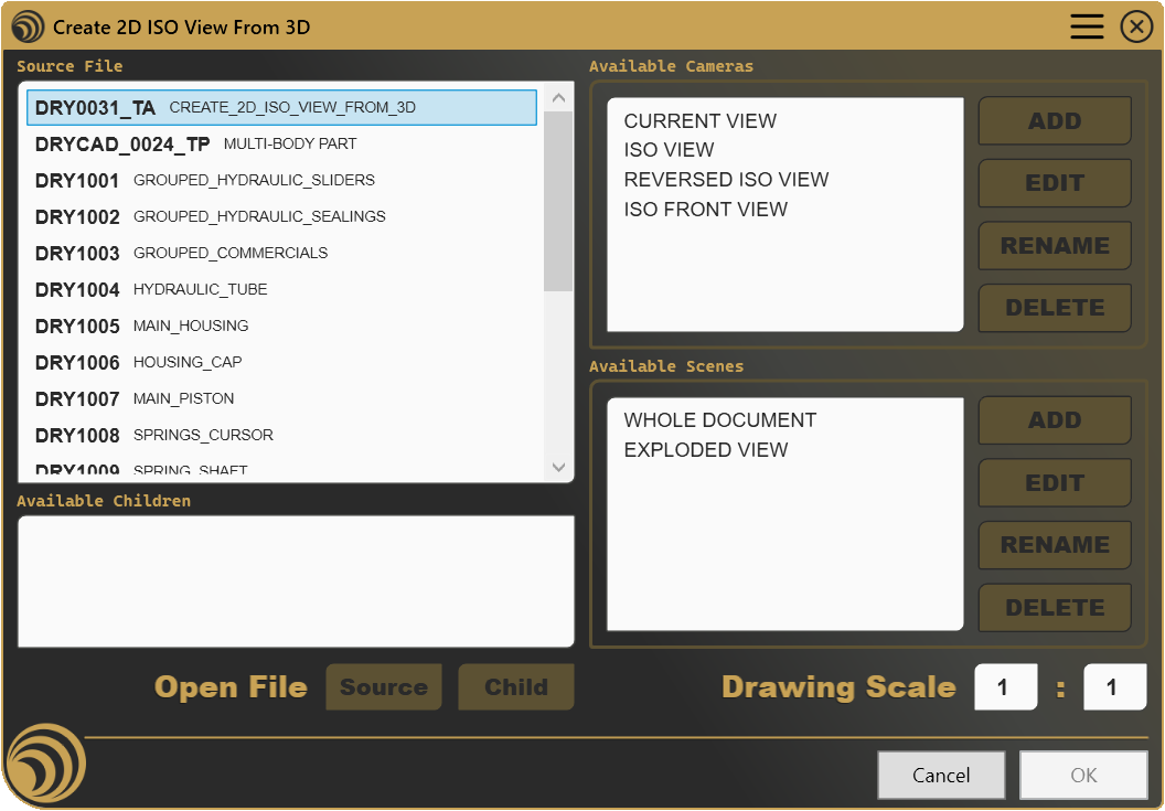
3.1 Source File and Available Children

The Source File list shows every open Part and Product document. If the tool is launched from an active Drawing, the document that the drawing’s views are already linked to is detected automatically and placed at the top of the list as the current selection.
The Available Children list shows related files that share a naming pattern with the selected source, according to your configuration (see Section 4), for example, variant or reference files stored alongside the original. If a source has related children, the source itself is also listed here (under its configured display name) so you can choose between generating the view from the parent or from one of its children.
| Control | Description |
|---|---|
| Source File list | Selects which open document to use as the base for camera and scene lookup |
| Available Children list | When populated, lets you redirect the view generation to a related child file instead of the source itself |
| Open File, Source | Opens the selected source document as an active window in CATIA |
| Open File, Child | Opens the selected child document as an active window in CATIA |
Selecting a different Source File or Available Child immediately refreshes both the Available Cameras and Available Scenes lists to match the newly selected document.
Both Open File buttons are only enabled when the corresponding list has a selection and that document isn’t already open in its own window, reopening an already-open document is unnecessary, so the buttons stay disabled once a window exists for the current selection.
Why is Open File disabled?
- No item is selected in the Source File or Available Children list
- The selected document is already open in its own CATIA window
3.2 Available Cameras

The camera list always includes the current 3D viewpoint (only when the source document has an open window), a standard isometric view, and a reverse isometric view, computed geometrically rather than read from the model. Any named custom camera already defined in the source document is listed alongside these, using its actual name.
| Control | Description |
|---|---|
| ADD | Prompts for a name and creates a new custom camera from the current 3D viewpoint |
| EDIT | Updates the selected custom camera’s viewpoint to match the current 3D view, after a confirmation prompt |
| RENAME | Prompts for a new name for the selected custom camera |
| DELETE | Removes the selected custom camera, after a confirmation prompt |
ADD is only enabled when the current workspace is a Part or Product, it is disabled entirely when the tool is launched against a Drawing document, since there is no 3D viewpoint of the Drawing itself to capture.
EDIT and DELETE are only enabled when a camera is selected and that camera is a custom one, the built-in Current View, Isometric, and Reverse Isometric entries can’t be edited or deleted, since they aren’t real camera objects in the document but computed on the fly.
Why is ADD disabled?
- The current document is a Drawing rather than a Part or Product
Why are EDIT / DELETE disabled?
- No camera is selected in the Available Cameras list
- The selected entry is one of the built-in views (Current View, Isometric, Reverse Isometric) rather than a named custom camera
Note: RENAME follows the same enablement logic as EDIT and DELETE in practice, since it also requires a genuine custom camera to act on.
3.3 Available Scenes

The scene list always includes a built-in “whole document” entry representing the complete, unfiltered structure, this entry cannot be edited, renamed, or deleted. For Product documents, any named scene already defined on the product is listed alongside it.
| Control | Description |
|---|---|
| ADD | Prompts for a name and creates a new, empty scene on the current Product |
| EDIT | Activates the selected scene for editing in CATIA, so its content can be adjusted |
| RENAME | Prompts for a new name for the selected scene |
| DELETE | Removes the selected scene, after a confirmation prompt |
ADD is only enabled when the current document is a Product, scenes are a Product-level concept in CATIA and don’t apply to standalone Parts.
EDIT, RENAME, and DELETE are only enabled when the current document is a Product, a scene is selected, and that scene is editable, the built-in “whole document” entry is explicitly marked as non-editable, since it isn’t a real ProductScene object but a synthetic default.
The Available Scenes list itself is only selectable when more than one scene exists, with just the default “whole document” entry present, there’s nothing meaningful to choose between, so the list stays disabled until at least one custom scene has been added.
Why is ADD disabled?
- The current document is a Part or a Drawing rather than a Product
Why are EDIT / RENAME / DELETE disabled?
- The current document is not a Product
- No scene is selected
- The selected scene is the built-in “whole document” entry, which cannot be modified
Why is the scene list itself not selectable?
- Only the default “whole document” scene exists, add a custom scene first with ADD
3.4 Drawing Scale
The Drawing Scale fields set the scale applied to the generated view, expressed as a numerator and denominator (e.g. 1 : 2). Both fields accept whole numbers only.
These fields are only enabled when the tool is operating on an active Drawing document, when launched from a Part or Product without a Drawing open, there’s no sheet yet to place a scaled view onto, so the scale has no meaning until a Drawing is active.
Why are the Drawing Scale fields disabled?
- No Drawing document is currently active, open or switch to a Drawing to set the scale
3.5 Cancel / OK
| Button | Action |
|---|---|
| Cancel | Closes the panel without making any changes. |
| OK | Generates the isometric view on the active drawing sheet using the selected source, camera, scene, and scale, then closes the panel. Also triggered by pressing Enter. |
OK is disabled unless every one of the following is set: a source document (or child) is selected, a camera is selected, a scene is selected, and both scale fields have a value. All five conditions must be satisfied simultaneously, there’s no partial generation.
Why is OK disabled?
- No source document (or child) is selected in the left column
- No camera is selected in Available Cameras
- No scene is selected in Available Scenes, remember that with only the default scene present, the list may not even be selectable yet (see Section 3.3)
- The Drawing Scale numerator or denominator is empty
4. Configuration: settings.ini
File Location
<install_folder>/DRY0031/settings.iniCan also be opened directly via Open Settings in the DRYCAD Menu (see Section 2), or reset via Clear Settings.
Structure
; ----------------------------------------------------
; DRY0031 - CREATE 2D ISO VIEW FROM 3D - SETTINGS FILE
; ----------------------------------------------------

[Description]
; Part Description Source
; (1: Definition, 2: DescriptionInst, 3: DescriptionRef, 4: Name [default], 5: Nomenclature, 6: Filename, 7: Custom)
PART_DESCRIPTION_SOURCE=3

; Product Description Source
; (1: Definition, 2: DescriptionInst, 3: DescriptionRef, 4: Name [default], 5: Nomenclature, 6: Filename, 7: Custom)
PRODUCT_DESCRIPTION_SOURCE=3

; Part Custom Description Property (if PART_DESCRIPTION_SOURCE = 7)
PART_CUSTOM_DESCRIPTION_PROPERTY=""

; Product Custom Description Property (if PRODUCT_DESCRIPTION_SOURCE = 7)
PRODUCT_CUSTOM_DESCRIPTION_PROPERTY=""

; Missing Description Value
MISSING_DESCRIPTION_VALUE="No Description..."

[Children Management]
; Method to identify possible Children from the current filename.
; e.g. Selected Filename is DRY0001.CATPart, you could have the following options:
; 0: No children [default]
; 1: Files that Start with the same name, e.g. DRY0001_1.CATPart
; 2: Files that End with the same name, e.g. REF_DRY0001.CATPart
; 3: Files that Contain the same name, e.g. REF_DRY0001_1.CATPart
CHILDREN_NAME_IDENTIFIER=1

; Folder where to search for childre, leave empty to use the same folder of the source File
CHILDREN_FOLDER=

[Naming Conventions]
; Children Source Displayed Name
CHILDREN_SOURCE_NAME="DOCUMENTO ORIGINALE"

; Current View Displayed Name
CURRENT_VIEW_NAME="VISTA CORRENTE"

; Isometric View Displayed Name
ISOMETRIC_VIEW_NAME="VISTA ISO"

; Reversed Isometric View Displayed Name
REVERSED_ISOMETRIC_VIEW_NAME="VISTA ISO ROVESCIATA"

; Whole Document Scene Displayed Name
WHOLE_DOCUMENT_SCENE_NAME="DOCUMENTO COMPLETO"

[Output Drawing View]
; Custom XML Styling file (Specify the custom XML styling file if available)
CUSTOM_XML_STYLING=

; View Name
; Use the following Placeholders to compose the name:
; [PARTNUMBER] = PartNumber]
; [NAME] = Part Name
; [DESCRIPTION] = Part Description
; [CAMERA] = Selected Camera Name
; [SCENE] = Selected Scene Name
VIEW_NAME="[PARTNUMBER] - [SCENE]: VISTA ISOMETRICA"
Lines starting with ; are comments and are ignored.
Parameters
PART_DESCRIPTION_SOURCE
| Property | Value |
|---|---|
| Section | [Description] |
| Type | Integer (1–7) |
| Required | No |
| Default | 4 (Name) |
Determines which CATIA property is used as the description for Part documents in the Source File and Available Children lists.
; 1 = Definition, 2 = DescriptionInst, 3 = DescriptionRef,
; 4 = Name (default), 5 = Nomenclature, 6 = Filename, 7 = Custom
PART_DESCRIPTION_SOURCE=3
PRODUCT_DESCRIPTION_SOURCE
| Property | Value |
|---|---|
| Section | [Description] |
| Type | Integer (1–7) |
| Required | No |
| Default | 4 (Name) |
Determines which CATIA property is used as the description for Product documents. Same value options as PART_DESCRIPTION_SOURCE.
PRODUCT_DESCRIPTION_SOURCE=3PART_CUSTOM_DESCRIPTION_PROPERTY
| Property | Value |
|---|---|
| Section | [Description] |
| Type | String |
| Required | Only if PART_DESCRIPTION_SOURCE=7 |
| Default | (empty) |
The name of the custom property to read as the Part description when PART_DESCRIPTION_SOURCE is set to 7 (Custom).
PART_CUSTOM_DESCRIPTION_PROPERTY="ProjectCode"PRODUCT_CUSTOM_DESCRIPTION_PROPERTY
| Property | Value |
|---|---|
| Section | [Description] |
| Type | String |
| Required | Only if PRODUCT_DESCRIPTION_SOURCE=7 |
| Default | (empty) |
The name of the custom property to read as the Product description when PRODUCT_DESCRIPTION_SOURCE is set to 7 (Custom).
PRODUCT_CUSTOM_DESCRIPTION_PROPERTY="ProjectCode"MISSING_DESCRIPTION_VALUE
| Property | Value |
|---|---|
| Section | [Description] |
| Type | String |
| Required | No |
| Default | (empty) |
The placeholder text shown in the document lists when the configured description source returns no value.
MISSING_DESCRIPTION_VALUE="No Description..."CHILDREN_NAME_IDENTIFIER
| Property | Value |
|---|---|
| Section | [Children Management] |
| Type | Integer (0–3) |
| Required | No |
| Default | 0 (No children) |
Controls how related child files are matched against the selected source document’s file name.
; 0 = No children [default]
; 1 = Files that Start with the same name, e.g. DRY0001_1.CATPart
; 2 = Files that End with the same name, e.g. REF_DRY0001.CATPart
; 3 = Files that Contain the same name, e.g. REF_DRY0001_1.CATPart
CHILDREN_NAME_IDENTIFIER=1
CHILDREN_FOLDER
| Property | Value |
|---|---|
| Section | [Children Management] |
| Type | String (folder path) |
| Required | No |
| Default | (empty, uses the source document’s own folder) |
The folder searched for related child files. When left empty, the tool searches the same folder as the selected source document.
CHILDREN_FOLDER="D:\Projects\References"CHILDREN_SOURCE_NAME
| Property | Value |
|---|---|
| Section | [Naming Conventions] |
| Type | String |
| Required | No |
| Default | "ORIGIN SOURCE" |
The display name used for the original source document when it’s listed inside Available Children (only shown when the source has at least one detected child).
CHILDREN_SOURCE_NAME="DOCUMENTO ORIGINALE"CURRENT_VIEW_NAME
| Property | Value |
|---|---|
| Section | [Naming Conventions] |
| Type | String |
| Required | No |
| Default | "CURRENT VIEW" |
The display name used for the built-in entry representing the source document’s current 3D viewpoint in Available Cameras.
CURRENT_VIEW_NAME="VISTA CORRENTE"ISOMETRIC_VIEW_NAME
| Property | Value |
|---|---|
| Section | [Naming Conventions] |
| Type | String |
| Required | No |
| Default | "ISO VIEW" |
The display name used for the built-in standard isometric entry in Available Cameras.
ISOMETRIC_VIEW_NAME="VISTA ISO"REVERSED_ISOMETRIC_VIEW_NAME
| Property | Value |
|---|---|
| Section | [Naming Conventions] |
| Type | String |
| Required | No |
| Default | "REVERSE ISO VIEW" |
The display name used for the built-in reverse isometric entry in Available Cameras.
REVERSED_ISOMETRIC_VIEW_NAME="VISTA ISO ROVESCIATA"WHOLE_DOCUMENT_SCENE_NAME
| Property | Value |
|---|---|
| Section | [Naming Conventions] |
| Type | String |
| Required | No |
| Default | "WHOLE SCENE" |
The display name used for the built-in, non-editable scene entry representing the complete document structure in Available Scenes.
WHOLE_DOCUMENT_SCENE_NAME="DOCUMENTO COMPLETO"CUSTOM_XML_STYLING
| Property | Value |
|---|---|
| Section | [Output Drawing View] |
| Type | String (file path) |
| Required | No |
| Default | (empty, no custom styling applied) |
Path to a custom XML styling file applied to the generated drawing view. If the file cannot be applied, the view is still generated without custom styling.
CUSTOM_XML_STYLING="D:\Standards\view_style.xml"VIEW_NAME
| Property | Value |
|---|---|
| Section | [Output Drawing View] |
| Type | String (template with placeholders) |
| Required | No |
| Default | (empty, falls back to "ISOMETRIC VIEW") |
The template used to compose the name of each generated drawing view. Supports the following placeholders, replaced case-insensitively:
; [PARTNUMBER] = Part Number of the source document
; [NAME] = Name of the source document
; [DESCRIPTION] = Description of the source document (per PART/PRODUCT_DESCRIPTION_SOURCE)
; [CAMERA] = Name of the selected camera
; [SCENE] = Name of the selected scene
VIEW_NAME="[PARTNUMBER] - [SCENE]: VISTA ISOMETRICA"
5. Examples
Example 1, Single Part, Quick Isometric
A designer working on a single Part who just needs a fast isometric view on the drawing sheet, without any prior camera setup.
[Naming Conventions]
CURRENT_VIEW_NAME="Current View"
ISOMETRIC_VIEW_NAME="Isometric"
REVERSED_ISOMETRIC_VIEW_NAME="Reverse Isometric"
WHOLE_DOCUMENT_SCENE_NAME="Full Model"

[Output Drawing View]
VIEW_NAME="[NAME] - ISO"
What it creates: With no custom cameras defined, the Available Cameras list shows only the three built-in entries. Selecting Isometric and confirming generates a view named e.g. Bracket_v3 - ISO.
Key points:
- No preparation is required for this scenario, the built-in Isometric and Reverse Isometric views are always available
- Since the source is a Part, Available Scenes only shows the default “Full Model” entry, and the scene list stays non-selectable, that’s expected, not an error
[NAME]in the template resolves to the Part’s document name
Example 2, Assembly with Named Scenes for Different Drawing Sheets
A team documenting a complex assembly, where different drawing sheets need to show different subsets of components (e.g. full assembly vs. a specific sub-mechanism), each from a consistent isometric angle.
[Naming Conventions]
CURRENT_VIEW_NAME="Live Viewpoint"
ISOMETRIC_VIEW_NAME="Standard ISO"
REVERSED_ISOMETRIC_VIEW_NAME="Reverse ISO"
WHOLE_DOCUMENT_SCENE_NAME="Complete Assembly"

[Output Drawing View]
VIEW_NAME="[PARTNUMBER] - [SCENE] - [CAMERA]"
What it creates: Two scenes, Complete Assembly (built-in) and a custom Drive Train Only scene created ahead of time with ADD, combined with the Standard ISO camera produce two clearly named, repeatable views: ASM-1002 - Complete Assembly - Standard ISO and ASM-1002 - Drive Train Only - Standard ISO.
Key points:
CanAddSceneonly allows scene creation on Product documents, the custom scene has to be prepared while the Product itself is the active document, before switching to the Drawing- Once at least one custom scene exists alongside the built-in one, Available Scenes becomes selectable
- Naming the view template with
[SCENE]and[CAMERA]keeps every generated view self-descriptive in the CATIA specification tree
Example 3, Reusing a Custom Camera Across Multiple Child Variants
A source Part has several child variants stored alongside it (e.g. different finishes of the same component), and every variant should be documented from the exact same custom angle.
[Children Management]
CHILDREN_NAME_IDENTIFIER=1
CHILDREN_FOLDER=

[Naming Conventions]
CHILDREN_SOURCE_NAME="Base Version"

[Output Drawing View]
VIEW_NAME="[PARTNUMBER] - [DESCRIPTION]"
What it creates: With CHILDREN_NAME_IDENTIFIER=1, files whose names start with the same base name as the source (e.g. Bracket.CATPart and Bracket_Painted.CATPart) appear together in Available Children, with the original listed as Base Version. A custom camera named Standard Angle created once on the base Part is then reused: selecting each child in turn and generating the view with the same camera produces consistent isometric views for every variant.
Key points:
- The custom camera only needs to exist on the document actually used as the generation source, verify it’s visible in Available Cameras for the selected child before relying on it
CHILDREN_FOLDERleft empty means the search happens in the same folder as the source file, set it explicitly if variants live elsewhere- This workflow saves the most time precisely because the camera setup happens once, not once per variant
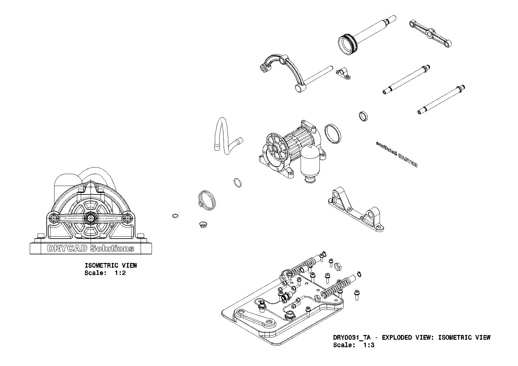
Result in the CATIA tree:
6. Troubleshooting
”User not found. Please login and try again.”
The tool could not identify the logged-in user at startup. Log out of the DRYCAD Suite, log back in, and relaunch.
”CATIA is not open. Please open CATIA and try again.”
The tool launched but could not find a running CATIA V5 process. Make sure CATIA is fully loaded before clicking the CommandBar button.
”Invalid Workspace”
The active document is not a Part, Product, or Drawing. Switch to or open one of these document types in CATIA, then relaunch.
Panel closes unexpectedly without any action
A background check detected that CATIA has closed, or the active document is no longer a supported workspace type. This is expected behavior, return to a Part, Product, or Drawing document and reopen the panel.
The OK button stays disabled
Check all of the following:
- A document must be selected in Source File (or, if applicable, in Available Children)
- A camera must be selected in Available Cameras
- A scene must be selected in Available Scenes, if the list isn’t selectable yet, only the default scene exists; add a custom one first if you need to isolate specific components
- Both Drawing Scale fields must have a value, this in turn requires an active Drawing document
ADD / EDIT / DELETE are disabled for cameras
- ADD requires the current document to be a Part or Product, it’s unavailable when working directly from a Drawing, since there’s no 3D viewpoint of a Drawing to capture as a camera
- EDIT and DELETE require a camera to be selected, and specifically a named custom camera, the built-in Current View, Isometric, and Reverse Isometric entries are computed on the fly and can’t be modified or removed
ADD / EDIT / RENAME / DELETE are disabled for scenes
- All four require the current document to be a Product, scenes don’t apply to standalone Parts
- EDIT, RENAME, and DELETE additionally require a scene to be selected, and specifically one that isn’t the built-in “whole document” entry
- If the Available Scenes list itself won’t let you select anything, only the default entry exists yet, use ADD first
The generated view doesn’t reflect the intended camera angle
Confirm that the camera actually belongs to the document used as the generation source, if a child document was selected instead of the base source, its own cameras (not the parent’s) are what populate Available Cameras. If you edited a camera expecting it to update, remember EDIT overwrites the camera’s viewpoint with whatever the active 3D view currently shows at the moment you confirm, position the view first, then click EDIT.
Custom styling isn’t applied to the generated view
If CUSTOM_XML_STYLING points to a file that can’t be applied, the tool silently continues without it rather than failing the whole operation. Verify the path is correct and the file is a valid styling definition for drawing views.
7. Version History
| Version | Date | Changes |
|---|---|---|
| 1.0.0 | 2026-06 | Initial release |
DRY0031, Create 2D ISO View From 3D | DRYCAD Solutions | v1.0.0