
DRYCAD Suite | User Documentation | v1.0.0
Table of Contents
- Overview
- Getting Started
- User Interface
- Configuration: settings.ini
- Examples
- Troubleshooting
- Version History
1. Overview
Coordinates arrive in every format except the one your Part actually understands. DRY0033 closes that gap in both directions: import a table of XYZ values from Excel or CSV straight into a Geometrical Set as real 3D points, or export points already in the model out to a spreadsheet or text file. One panel, one Mode toggle, same reliable result whether you’re bringing data in or sending it out.
What it does:
- Imports XYZ coordinates (and optionally names) from an Excel range or a CSV file, creating 3D points inside a selected Geometrical Set or Ordered Geometrical Set
- Exports existing points from a Geometrical Set to Excel or CSV, with optional point names
- Measures and writes coordinates relative to the Part origin by default, or any Axis System you select
- Connects freshly imported points with a Polyline or Spline automatically, if requested
- Reads a range directly from an already-open Excel workbook, or opens a file/range picker otherwise
- Reports how many rows were analyzed, how many points succeeded, and how many rows failed on every import
Supported CAD platforms: CATIA V5
Workspace requirement: An active Part document must be open in CATIA.
2. Getting Started
Prerequisites
- CATIA V5 must be running
- You must be logged into the DRYCAD Suite
- An active Part document must be open in CATIA
- For Excel-based import/export: Microsoft Excel must be installed
Launching the Tool
DRY0033 is launched from the DRYCAD Suite CommandBar inside CATIA V5. Click the corresponding button to open the panel.
The tool checks the following conditions at startup, and will show an error and close if any fail:
- A valid user session is found, if not: “User not found. Please login and try again.”
- CATIA V5 is running and accessible, if not: “CATIA is not open. Please open CATIA and try again.”
- The active document is a Part, if not, an “Invalid Workspace” error is shown and the panel does not open
A background watchdog checks every 5 seconds whether CATIA is still running and whether the active document is still a Part. If either condition changes, the panel closes automatically.
The DRYCAD Menu
Every DRYCAD Suite tool with a user interface includes a menu in the top bar, accessed via the hamburger icon next to the window controls.

| Option | Description |
|---|---|
| Release 1.0.0 | Displays the current version of the tool. Informational only, not an action. |
| Documentation | Opens this documentation page in your default browser. |
| Open Settings | Opens settings.ini in your system’s default text editor. |
| Clear Settings | Resets settings.ini to a clean default version. Shows a confirmation warning before proceeding. |
3. User Interface
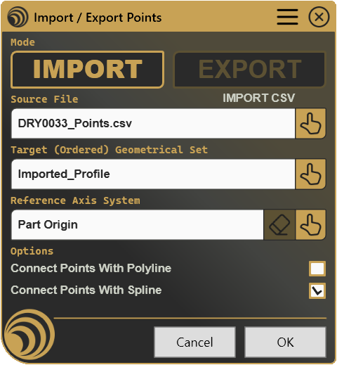
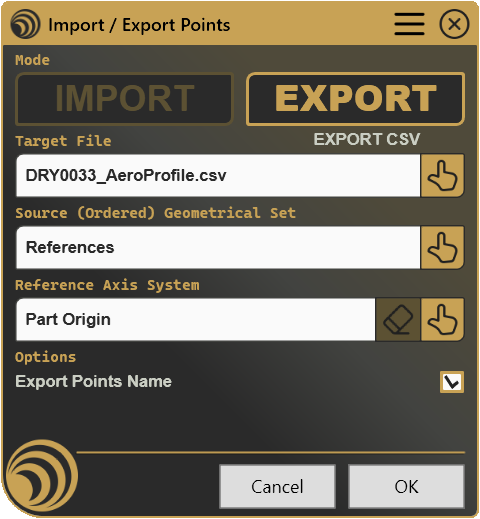
The panel starts with the Mode toggle at the top, followed by the file target, the Geometrical Set target, the reference axis system, mode-specific options, and finally Cancel/OK. Labels throughout the panel (file prefix, Geometrical Set prefix) switch automatically between Source and Target depending on the active mode, and the Options block at the bottom shows entirely different controls depending on which mode is active, Import and Export are, in effect, two different panels sharing the same frame.
3.1 Mode

Two toggle buttons set the direction of the operation. Only one can be active at a time.
| Control | Description |
|---|---|
| IMPORT | Reads coordinates from a file or Excel range and creates points in the Part |
| EXPORT | Reads existing points from the Part and writes their coordinates to a file |
Switching Mode relabels the File and Geometrical Set sections (Source File / Target Geometrical Set for Import, Target File / Source Geometrical Set for Export), clears the currently selected file, and swaps which options block is shown below. The file and Geometrical Set selection buttons, described next, are disabled until a Mode is chosen.
Why are the file, Geometrical Set, and axis system Select buttons disabled?
- No Mode is selected yet, Import or Export must be active before any selection button becomes usable
3.2 File Selection

| Control | Icon | Description |
|---|---|---|
| Select |  | Opens a file picker (Import: existing Excel/CSV file; Export: new or existing Excel/CSV file), or offers to use the active Excel range if a workbook is already open |
If an Excel workbook is already open when you click Select, the tool asks whether to use a range from that workbook instead of browsing for a file. Answering yes hands control to a manual range selection inside Excel; answering no (or if no workbook is open) opens the standard file picker instead, filtered to Excel (.xls, .xlsx, .xlsm) and CSV (.csv) files. The read-only field above the button shows the selected file name, and a small label to its right reports the detected mode and file type (e.g. “IMPORT CSV”).
The Select button itself follows the same enablement rule as every selection control in this tool: it needs an active Mode. See 3.1 if it appears greyed out.
3.3 Geometrical Set Selection
The Select button here prompts you to pick a Geometrical Set or Ordered Geometrical Set directly in the CATIA specification tree.
| Control | Icon | Description |
|---|---|---|
| Select | | Prompts you to click a Geometrical Set or Ordered Geometrical Set in CATIA |
For Import, this is the Target, the container that will receive the newly created points, and that becomes the active In Work Object once points are added. For Export, this is the Source, every point found anywhere inside it (searched recursively through the whole container, not just its top level) is measured and included in the output. Whether the container is a plain Geometrical Set or an Ordered Geometrical Set determines how imported points are inserted: appended for a Geometrical Set, inserted in sequence for an Ordered Geometrical Set.
Like file selection, this button is only enabled once a Mode is active.
3.4 Reference Axis System

| Control | Icon | Description |
|---|---|---|
| Clear |  | Resets the reference back to the Part origin |
| Select | | Prompts you to click an Axis System in CATIA to use as the coordinate reference |
By default, coordinates are read and written relative to the Part origin, shown in the field as “Part Origin”. Selecting an Axis System changes the frame of reference: on export, exported coordinates are transformed into that system before being written to the file; on import, newly created points are associated with that Axis System as their reference. Choosing a reference axis system is optional in both directions, the tool works perfectly well against the Part origin alone. This row’s behavior does not change between Import and Export; only its effect on the resulting coordinates does.
Unlike file and Geometrical Set selection, the Select button for the axis system is not gated by Mode, it can be used at any time. The Clear button, however, has its own separate condition.
Why is Clear disabled?
- No Axis System has been selected yet, the reference is already at the default Part origin, so there is nothing to clear
3.5 Options, Import Mode

This block replaces the Export options below the moment IMPORT becomes the active Mode; the two option sets never appear together.
| Control | Description |
|---|---|
| Connect Points With Polyline | Links all imported points, in file order, with a single open polyline |
| Connect Points With Spline | Links all imported points, in file order, with a single open spline |
The two checkboxes are mutually exclusive, checking one automatically unchecks the other. Leaving both unchecked imports the points with no connecting geometry at all. Either connection is created as a separate feature inside the same target Geometrical Set, immediately after all points have been added.
3.6 Options, Export Mode

This block replaces the Import options above the moment EXPORT becomes the active Mode.
| Control | Description |
|---|---|
| Export Points Name | Adds a fourth column containing each point’s name to the exported file |
Leaving this unchecked exports only X, Y, and Z coordinates. There is no equivalent to the Import mode’s connection checkboxes here, Export never creates or modifies geometry in the Part, it only reads and writes coordinates.
3.7 Cancel / OK
| Button | Action |
|---|---|
| Cancel | Closes the panel without making any changes, releasing any Excel connection that was opened. |
| OK | Runs the import or export, shows a summary message if there is one to show, and closes the panel. Also triggered by pressing Enter. |
OK performs the actual read or write operation and reports back: on import, a message states how many rows were analyzed, how many points were created, and how many rows failed to parse; on export, a failure to find any points in the selected container is reported instead of a silent empty file.
Why is OK disabled?
- No Mode is selected, Import or Export must be active
- No file has been selected yet
- No Geometrical Set (or Ordered Geometrical Set) has been selected yet
Note that selecting a reference Axis System is never required for OK to become available, it only affects the coordinates used, not whether the operation can run.
4. Configuration: settings.ini
File Location
<install_folder>/DRY0033/settings.iniCan also be opened directly via Open Settings in the DRYCAD Menu (see Section 2), or reset via Clear Settings.
Structure
; ------------------------------------------------
; DRY0033 - IMPORT / EXPORT POINTS - SETTINGS FILE
; ------------------------------------------------

[Panel Settings]
; Starting Action (0: None [default], 1: Import, 2: Export)
STARTING_ACTION=1

; Default Axis System Displayed Name
DEFAULT_AXIS_SYSTEM_NAME="Part Origin (Default AXSYS)"

[Import Settings]
; CSV Files Separator Char (By default, is comma ',')
CSV_SEPARATOR_CHAR=

[Export Settings]
; Add Table Headers (0: False [default], 1: True)
ADD_TABLE_HEADERS=1

; Header X Coordinate Column Name
HEADER_X_COLUMN_NAME="X Pos [mm]"

; Header Y Coordinate Column Name
HEADER_Y_COLUMN_NAME="Y Pos [mm]"

; Header Z Coordinate Column Name
HEADER_Z_COLUMN_NAME="Z Pos [mm]"

; Header Point Name Column Name
HEADER_POINT_NAME_COLUMN_NAME="Name"

; Number Precision (decimal points, default is 3)
NUMBER_PRECISION=5
Lines starting with ; are comments and are ignored.
Parameters
STARTING_ACTION
| Property | Value |
|---|---|
| Section | [Panel Settings] |
| Type | Integer (0–2) |
| Required | No |
| Default | 0 |
Controls which Mode is pre-selected when the panel opens.
; 0 = None (no mode pre-selected)
; 1 = Import
; 2 = Export
STARTING_ACTION=1
DEFAULT_AXIS_SYSTEM_NAME
| Property | Value |
|---|---|
| Section | [Panel Settings] |
| Type | String |
| Required | No |
| Default | "Part Origin" |
The text shown in the axis system field before any Axis System has been selected.
DEFAULT_AXIS_SYSTEM_NAME="Part Origin (Default AXSYS)"CSV_SEPARATOR_CHAR
| Property | Value |
|---|---|
| Section | [Import Settings] |
| Type | String (single character) |
| Required | No |
| Default | , |
The character used both to split incoming CSV rows on import and to separate values on CSV export. Left empty in the default settings.ini, which falls back to a comma.
; Results in: 12.500,34.100,0.000
CSV_SEPARATOR_CHAR=","

; Results in: 12.500;34.100;0.000
CSV_SEPARATOR_CHAR=";"
ADD_TABLE_HEADERS
| Property | Value |
|---|---|
| Section | [Export Settings] |
| Type | Boolean (0 / 1) |
| Required | No |
| Default | 0 |
When set to 1, a header row (or header cells, for Excel) is written before the point data on export, using the column names configured below. Import is unaffected by this setting, incoming files are read purely by column position and count, with no header detection.
ADD_TABLE_HEADERS=1HEADER_X_COLUMN_NAME
| Property | Value |
|---|---|
| Section | [Export Settings] |
| Type | String |
| Required | No |
| Default | "X" |
The column header written for the X coordinate when ADD_TABLE_HEADERS is 1.
HEADER_X_COLUMN_NAME="X Pos [mm]"HEADER_Y_COLUMN_NAME
| Property | Value |
|---|---|
| Section | [Export Settings] |
| Type | String |
| Required | No |
| Default | "Y" |
The column header written for the Y coordinate when ADD_TABLE_HEADERS is 1.
HEADER_Y_COLUMN_NAME="Y Pos [mm]"HEADER_Z_COLUMN_NAME
| Property | Value |
|---|---|
| Section | [Export Settings] |
| Type | String |
| Required | No |
| Default | "Z" |
The column header written for the Z coordinate when ADD_TABLE_HEADERS is 1.
HEADER_Z_COLUMN_NAME="Z Pos [mm]"HEADER_POINT_NAME_COLUMN_NAME
| Property | Value |
|---|---|
| Section | [Export Settings] |
| Type | String |
| Required | No |
| Default | "Name" |
The column header written for the point name column when ADD_TABLE_HEADERS is 1 and Export Points Name is checked.
HEADER_POINT_NAME_COLUMN_NAME="Name"NUMBER_PRECISION
| Property | Value |
|---|---|
| Section | [Export Settings] |
| Type | Integer (0–10) |
| Required | No |
| Default | 3 |
The number of decimal places used when writing coordinates on export, applied to both Excel and CSV output.
; Results in: 12.50000
NUMBER_PRECISION=5

; Results in: 12.500
NUMBER_PRECISION=3
5. Examples
Example 1, Importing Survey Points from CSV
A batch of surveyed points arrives as a semicolon-separated CSV file with names in the last column, and needs to be connected as a single reference polyline once imported.
[Panel Settings]
STARTING_ACTION=1
DEFAULT_AXIS_SYSTEM_NAME="Part Origin (Default AXSYS)"

[Import Settings]
CSV_SEPARATOR_CHAR=";"

[Export Settings]
ADD_TABLE_HEADERS=1
HEADER_X_COLUMN_NAME="X"
HEADER_Y_COLUMN_NAME="Y"
HEADER_Z_COLUMN_NAME="Z"
HEADER_POINT_NAME_COLUMN_NAME="Name"
NUMBER_PRECISION=3
What it creates: With IMPORT active, a CSV such as 12.500;34.100;0.000;P1 is read as a named point; checking Connect Points With Polyline before clicking OK links every imported point in file order.
Key points:
STARTING_ACTION=1opens the panel already in Import modeCSV_SEPARATOR_CHAR=";"matches the survey export format, avoiding a manual re-save- Whether a row has a name is detected automatically, no separate setting controls this, it depends purely on whether 3 or 4 values are present per line
Example 2, Exporting Points with Full Headers for a Report
A designer needs to hand off a list of reference point coordinates to a manufacturing partner as a clean, labeled Excel file.
[Panel Settings]
STARTING_ACTION=2
DEFAULT_AXIS_SYSTEM_NAME="Part Origin (Default AXSYS)"

[Import Settings]
CSV_SEPARATOR_CHAR=

[Export Settings]
ADD_TABLE_HEADERS=1
HEADER_X_COLUMN_NAME="X Pos [mm]"
HEADER_Y_COLUMN_NAME="Y Pos [mm]"
HEADER_Z_COLUMN_NAME="Z Pos [mm]"
HEADER_POINT_NAME_COLUMN_NAME="Point Name"
NUMBER_PRECISION=2
What it creates: With EXPORT active, selecting the point-holding Geometrical Set and checking Export Points Name, the resulting Excel file has a header row (X Pos [mm], Y Pos [mm], Z Pos [mm], Point Name) followed by one row per point, coordinates rounded to two decimals.
Key points:
STARTING_ACTION=2opens the panel already in Export mode, saving a click for a team that mostly exportsNUMBER_PRECISION=2keeps the report readable without excess decimal noise- Descriptive header names make the handoff file self-explanatory to someone outside the DRYCAD Suite
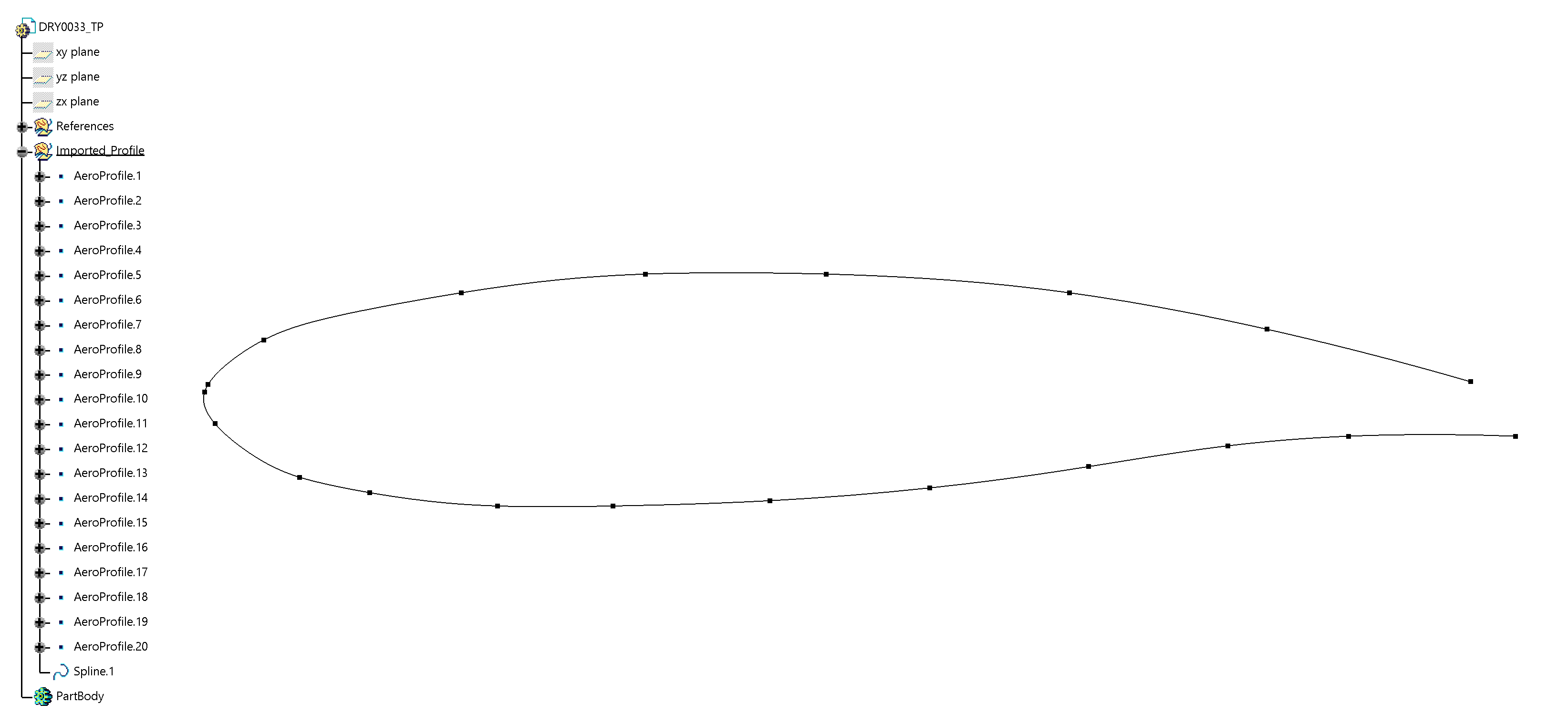
Result in the CATIA tree:
Example 3, Importing Against a Custom Axis System
A team builds fixtures relative to a local mounting frame rather than the Part origin, and always connects imported points with a smooth spline.
[Panel Settings]
STARTING_ACTION=1
DEFAULT_AXIS_SYSTEM_NAME="Part Origin (Default AXSYS)"

[Import Settings]
CSV_SEPARATOR_CHAR=","

[Export Settings]
ADD_TABLE_HEADERS=0
HEADER_X_COLUMN_NAME="X"
HEADER_Y_COLUMN_NAME="Y"
HEADER_Z_COLUMN_NAME="Z"
HEADER_POINT_NAME_COLUMN_NAME="Name"
NUMBER_PRECISION=4
What it creates: After selecting the mounting frame’s Axis System via Select in the Reference Axis System row, imported coordinates are interpreted relative to that frame instead of the Part origin; checking Connect Points With Spline links the resulting points into a single curve.
Key points:
- The Axis System selection is independent of
STARTING_ACTION, it must be picked manually each session unless the team standardizes on always selecting it before importing ADD_TABLE_HEADERS=0is irrelevant here since the workflow only imports, but is set for consistency in case the same settings file is later used for an exportNUMBER_PRECISION=4matters only for exports; imported values keep the full precision of the source coordinates
6. Troubleshooting
”User not found. Please login and try again.”
The tool could not identify the logged-in user at startup. Log out of the DRYCAD Suite, log back in, and relaunch.
”CATIA is not open. Please open CATIA and try again.”
The tool launched but could not find a running CATIA V5 process. Make sure CATIA is fully loaded before clicking the CommandBar button.
”Invalid Workspace”
The active document is not a Part. DRY0033 only operates on Part documents. Switch to or open a Part in CATIA, then relaunch.
Panel closes unexpectedly without any action
The background watchdog detected that CATIA has closed, or the active document is no longer a Part. This is expected behavior, the panel shuts down to avoid operating on an unsupported context. Return to a Part document and reopen the panel.
”Selected Geometrical Set contains no point to measure.”
On export, the chosen Geometrical Set (or Ordered Geometrical Set) was searched recursively and no Point objects were found inside it. Confirm you selected the container that actually holds the points, not an empty or unrelated one.
”Error converting the Axis System Coordinates of selected Points.”
The transformation of exported point coordinates into the selected Axis System failed. This can happen if the Axis System reference has become invalid since selection (for example, its supporting geometry was deleted). Reselect the Axis System, or clear it to fall back to the Part origin, then try again.
Import reports failed rows
Every row that fails to import is counted separately from successes and reported in the summary message after clicking OK. Rows fail for one of these reasons:
- The row does not have exactly 3 or 4 columns of data
- When 4 columns are present, none of the recognized name/coordinate arrangements could be parsed, check that exactly one of the four values is non-numeric (the name) and the other three are numeric
- One or more of the coordinate values could not be converted to a number (e.g. stray text, wrong decimal separator, or an empty cell)
Successfully parsed rows are still imported even if others in the same file fail, check the reported counts to confirm the result matches expectations.
Name detection picked the wrong column
When a row has 4 values, the tool decides which one is the name by testing whether the last value parses as a number. If it does not parse as a number, it’s treated as the name and the first three values as X, Y, Z. If the last value does parse as a number, the first value is instead treated as the name and the remaining three as coordinates. A row where both a numeric-looking name and a valid coordinate set could be read either way may import with the columns swapped from what was intended, keep the name consistently in the first or last column throughout the file to avoid ambiguity.
Excel range prompt appears unexpectedly
If Excel is already open when you click the file Select button, the tool always asks whether to use the active workbook’s range instead of opening a file browser. Answer No if you intended to pick a file from disk rather than a live selection.
Why is OK disabled?
- No Mode is selected, click IMPORT or EXPORT first
- No file has been selected, use the file Select button
- No Geometrical Set or Ordered Geometrical Set has been selected, use the corresponding Select button
7. Version History
| Version | Date | Changes |
|---|---|---|
| 1.0.0 | 2026-06 | Initial release |
DRY0033, Import / Export Points | DRYCAD Solutions | v1.0.0